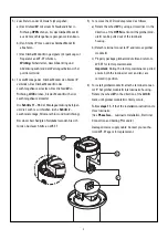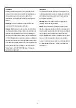
2
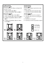
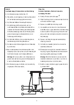
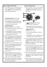
5) Zum Entfernen der LED wie folgt vorgehen:
a) Das Drehrad
W
mit einem Schraubendreher in
Richtung
OPEN
drehen, bis das Gimbal-Modul
X
aus dem Leuchtengehäuse gezogen werden kann.
b) Den Stecker
Y
lösen und das Gimbal-Modul
X
abnehmen.
c) Das Gimbal-Modul
X
in geeigneter Verpackung zur
Reparatur an WE-EF schicken.
Wichtig:
Sicherstellen, dass Abdeckring und
Abdeckung während der Wartungsarbeiten sicher
positioniert sind.
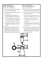
6) Für die Montage des Gimbal-Moduls den Stecker
Y
verbinden. Das Gimbal-Modul
X
in das
Leuchtengehäuse einsetzen. Das Drehrad
W
in
Richtung
LOCK
drehen, bis das Modul
X
sicher im
Leuchtengehäuse einrastet.
Die
Schritte 11– 16
der Montage anleitung befolgen,
um die Leuchte zu schließen (siehe
Schritt 2
–
Leuchtenmontage, Stromanschluss und Ausrichtung)
.
Bei einem beschädigten Netzkabel wenden Sie sich
für den Austausch bitte an WE-EF.
5) To remove the LED module proceed as follows:
a) Rotate the wheel
W
by using a screwdriver in the
direction of the
OPEN
mark until the gimbal mod-
ule
X
can be pulled out of the luminaire
housing.
b) Detach terminal connector
Y
and remove gimbal
module
X
.
c) Properly package gimbal module
X
and return to
WE-EF for factory-maintenance.
Important:
During the factory-maintenance period,
ensure both the luminaire cover and lens are
secured in position.
6) To install gimbal module
X
, attache terminal connec-
tor
Y
. Set gimbal module
X
into luminaire housing.
Rotate the wheel
W
in the direction of the
LOCK
mark until gimbal module
X
is firmly secure,
Follow
steps 11– 16
of the installation instructions to
close luminaire.
(See
Phase Two
– Luminaire Installation, Electrical
Connection and Aiming Procedure.)
Damaged mains supply cable: Contact your autho-
rised WE-EF agent for replacement.
<-Open
Loc
k->
<-Open
Loc
k->
Y
X
W


