


WS1 & WS1.25 Drawings & Service Manual
Problem
Possible Cause
Solution
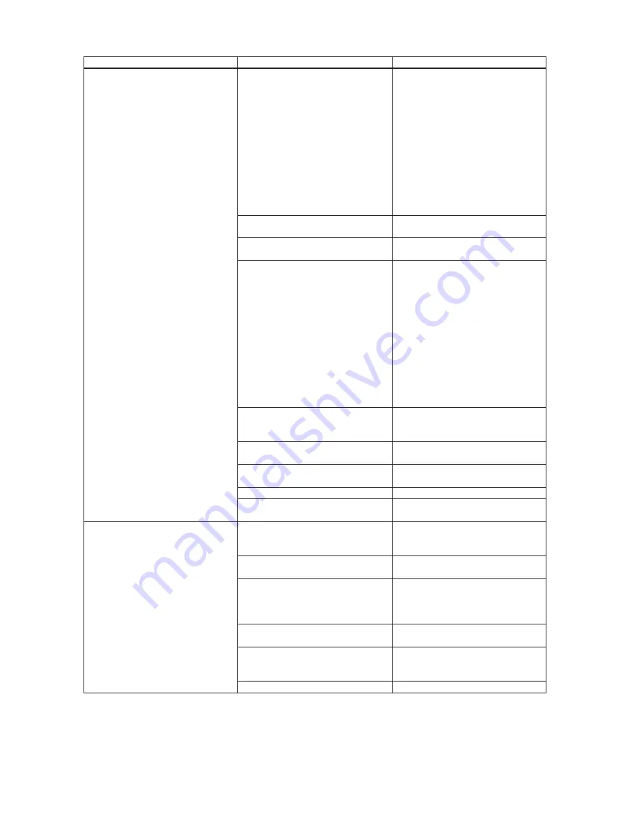
9. Error Codes
101, 1001 or E1 – Unable to recog-
nize start of regeneration
102, 1002 or E2 – Unexpected stall
103, 1003 or E3 – Motor ran to long,
timed out trying to reach next
cycle position
104, 1004 or E3 – Motor ran to long,
timed out trying to reach home
position
If other error codes display contact
the factory
a. Control valve has just been ser-
viced
a. Unplug power source jack from
the printed circuit board (black
wire) and plug back in or press
button sequence to reset valves:
TC valves (three buttons) press and
hold SET and DOWN buttons for 3
seconds. (Cover button may have
other names like “SET HOUR “,
“CLOCK” or “SET CLOCK” but the
circuit board is labeled with SET.)
All other valves press and hold
NEXT and REGEN buttons for 3
seconds.
b. Foreign matter is lodged in control
valve
b. Check piston and spacer stack
assembly for foreign matter
c. High drive forces on piston
c. Replace piston(s) and spacer
stack assembly
d. Control valve piston not in home
position
d. Unplug power source jack from
the printed circuit board (black
wire) and plug back in or press
button sequence to reset valves:
TC valves (three buttons) press and
hold SET and DOWN buttons for 3
seconds. (Cover button may have
other names like “SET HOUR “,
“CLOCK” or “SET CLOCK” but the
circuit board is labeled with SET.)
All other valves press and hold
NEXT and REGEN buttons for 3
seconds.
e. Motor not inserted fully to engage
pinion, motor wires broken or
disconnected, motor failure
e. Check motor and wiring. Replace
motor if necessary
f. Drive gear label dirty or damaged,
missing or broken gear
f. Replace or clean drive gear
g. Drive bracket incorrectly aligned
to back plate
g. Reseat drive bracket properly
h. PC board is damaged or defective
h. Replace PC board
i. PC board incorrectly aligned to
drive bracket
i. Ensure PC board is correctly
snapped on to drive bracket
10. Error Codes for MAV and
NHWB
106 or 1006 – MAV/NHWB unable
to
fi
nd proper park position, mo-
tor ran too long.
107 or 1007 – MAV/NHWB motor
ran too short (stalled) while
looking for proper park position
If other error codes display contact
the factory
a. Foreign matter is lodged in MAV/
NHWB
a. Check MAV/NHWB piston and
spacer stack assembly for foreign
matter
b. High drive forces on MAV/
NHWB piston
b. Replace MAV/NHWB piston and
spacer stack assembly
c. MAV/NHWB motor not inserted
fully to engage pinion, motor
wires broken or disconnected, mo-
tor failure
c. Check MAV/NHWB motor and
wiring. Check interconnect wir-
ing to both PC boards. Replace
motor or wiring if necessary.
d. MAV/NHWB drive gear damaged,
missing or broken gear
d. Replace MAV/NHWB drive cap.
e. MAV/NHWB main gear cover
assembly incorrectly aligned to
drive assembly.
e. Reseat MAV/NHWB main gear
cover assembly properly
f. PC board is damaged or defective
f. Replace PC board
Summary of Contents for EF Series
Page 20: ...Breaking a Salt Bridge...
Page 28: ......