6
www.waynepumps.com
Operating Instructions and Parts Manual
INSTALLATION (CONTINUED)
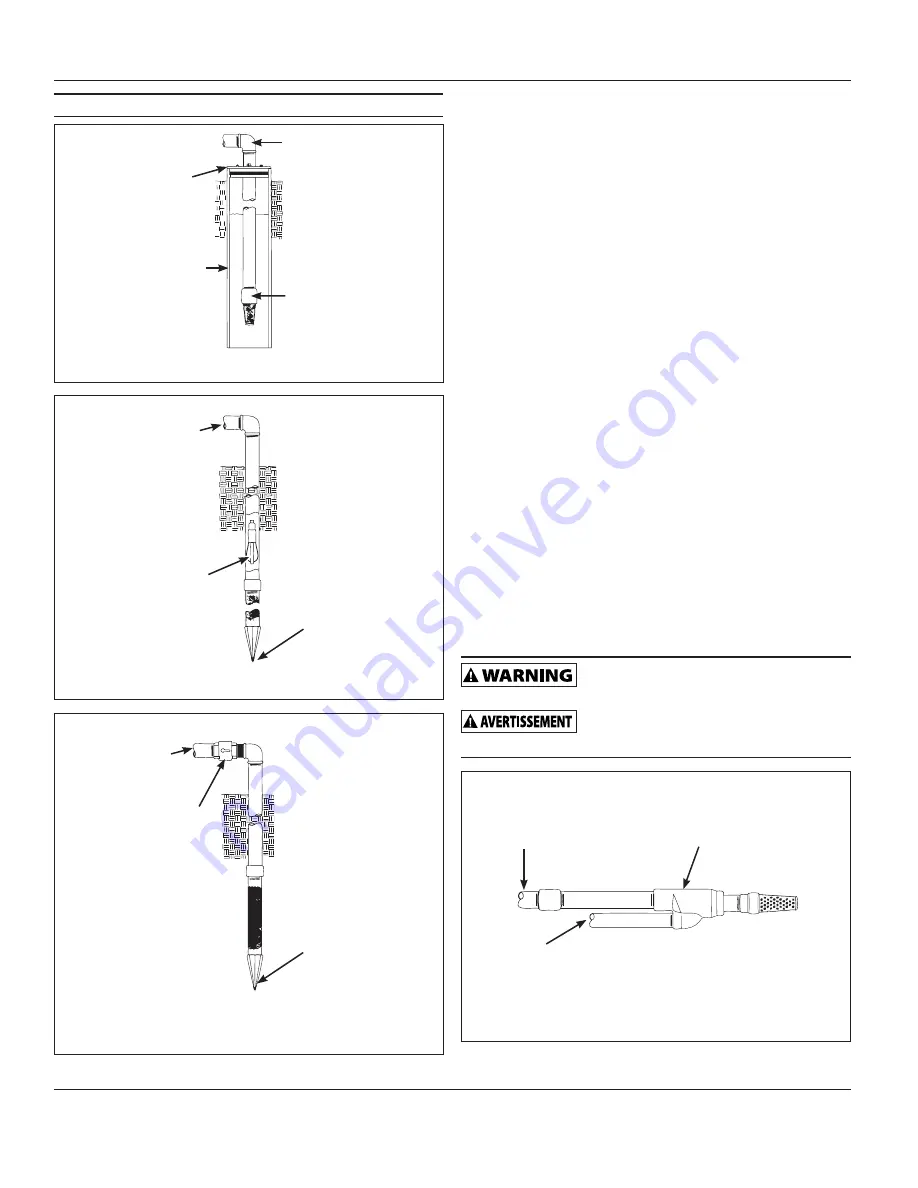
TO PUMP
WELL SEAL
FOOT VALVE
WELL CASING
ILLUSTRATION A
Figure 2
PACKER TYPE
FOOT VALVE
ILLUSTRATION B
TO PUMP
DRIVE POINT
Figure 2
TO PUMP
IN-LINE CHECK
VALVE
ILLUSTRATION C
DRIVE POINT
Figure 2
DEEP WELL INSTALLATION
DRILLED WELL (4 IN. OR LARGER) WITH TWO PIPE JET (FIGURE
16, ON PAGE 13 AND FIGURE 3, BELOW)
1. Assemble a 1-1/4 in. foot valve (not included) to the jet body. A 1-1/4
in. coupling is required to connect the larger pipe to the jet assembly.
2. Connect the 1 in. pipe threads into the smaller opening in the jet
body.
3. Lower the jet into the well. Add pipe as needed. Be sure to use pipe
joint compound, or plumber’s seal tape on all male threads.
4. Position the jet 10 - 20 feet below the lowest anticipated water level,
but never closer than 5 feet from the bottom of the well, if possible.
5. Install a well seal to support the pipe and prevent surface water and
other contaminants from entering the well.
6. Install the horizontal pipe from the well to the pump. Piping from the
vertical well pipe to the pump should never be smaller than the well
pipes.
7. Slope both pipes upward toward the pump to prevent trapping air. If
the horizontal distance exceeds 25 feet, see Chart 1, on page 7 for
the recommended pipe sizes.
DUG WELL, CISTERN, LAKE AND SPRING WITH TWO PIPE JET
(FIGURE 16, PAGE 13)
1. Install a 1-1/4 in. foot valve (not included) to the jet body. A 1-1/4 in.
coupling is required to connect the larger pipe to the jet assembly.
2. Connect the 1 in. pipe threads into the smaller opening in the jet
body.
3. Lower the jet into the water below the lowest anticipated water level,
but never closer than 18 in. from the bottom. Sand or debris may be
drawn into the system if the jet is too close to the bottom.
4. Provide protection for the jet and pipes against damage from boats
or swimmers if a lake is used for the water supply.
Install a screen around the inlet pipe to prevent
the entrapment of swimmers, wildlife and debris.
Installer un écran autour du tuyau d’entrée pour
éviter de piéger des nageurs, des animaux et des débris.
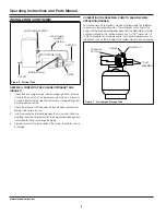
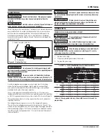
Figure 3 - Two Pipe Jet (4” Casing or Greater)
JET BODY
FOOT VALVE
1-1/4 IN. PIPE
1 IN. PIPE


