WarNING
WarNING
DO NOt raISe DOOr uNtIL HOrIzONtaL trackS are SecureD at rear, aS
OutLINeD IN SteP, rear Back HaNGS, Or DOOr cOuLD FaLL FrOM Over-
HeaD POSItION cauSING Severe Or FataL INJury.
Level the horizontal track assembly and bolt the horizontal track angle to the first encountered
slot in the flag angle using (1) 3/8”-16 x 3/4” truss head bolt and (1) 3/8”-16 hex nut. Repeat
for other side.
Remove the nail that was temporarily holding the top section in place, installed in step, Top
Section.
IMPOrtaNt:
FAILURE TO REMOVE NAIL BEFORE ATTEMPTING TO RAISE DOOR COULD CAUSE
PERMANENT DAMAGE TO TOP SECTION.
NOte:
If an idrive
®
opener will be installed, position horizontal tracks slightly above level.
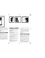
Horizontal
track
Flag angle
Quick
Install tab
Key slot
Quick
Install tab
in place
Tracks flush
3/8”-16
Hex nut
Horizontal track
angle
3/8”-16 x 3/4”
Truss head bolt
Flag angle
Horizontal tracks/F.a. Flag angles
Tools: Ratchet wrench, 7/16” Socket, 9/16” Socket, 9/16” Wrench,
level, Step ladder
17
NOte:
If you have Fully Adjustable flag angles, complete this step.
To install horizontal track, place the curved end over the top track roller of the top section. Align
the bottom of the horizontal track with the top of the vertical track. If you have Quick Install
horizontal track, tighten the horizontal track to the flag angle with a stud plate and (2) 1/4”-20
flange hex nuts. If you have Universal horizontal track, tighten the horizontal track to the flag
angle with (2) 1/4”-20 x 9/16” track bolts and (2) 1/4”-20 flange hex nuts.
WarNING
WarNING
DO NOt raISe DOOr uNtIL HOrIzONtaL trackS are SecureD at rear, aS
OutLINeD IN SteP, rear Back HaNGS, Or DOOr cOuLD FaLL FrOM Over-
HeaD POSItION cauSING Severe Or FataL INJury.
Level the horizontal track assembly and bolt the horizontal track angle to the first encountered
slot in the flag angle using (1) 3/8”-16 x 3/4” truss head bolt and (1) 3/8”-16 hex nut. Repeat
for other side.
Remove the nail that was temporarily holding the top section in place, installed in step, Top
Section.
IMPOrtaNt:
FAILURE TO REMOVE NAIL BEFORE ATTEMPTING TO RAISE DOOR COULD CAUSE
PERMANENT DAMAGE TO TOP SECTION.
NOte:
If an idrive
®
opener will be installed, position horizontal tracks slightly above level.
adjusting top Fixtures
Tools: 7/16” Wrench, Step ladder
18
With horizontal tracks installed, you can now adjust the top fixtures. Vertically align the top sec-
tion of the door with the lower sections. Once aligned, position the top fixture slide, out against
the horizontal track. Maintaining the slide’s position, tighten the (2) 1/4”-20 flange hex nuts to
secure the top fixture slide to the top fixture base. Repeat for other side.
torqueMaster
®
Spring tube
Tools: None
19
TorqueMaster
®
springs come lubricated and pre-assembled inside the TorqueMaster
®
spring
tube. To prepare for install, lay the spring tube assembly on the floor, inside garage, in front of
the door, and with the labeled end to the left.
TorqueMaster
®
spring tube
Label
center Bracket Bushing assembly
Tools: None
20
NOte:
If you are installing the idrive
®
opener with your garage door, skip this step and go to
your idrive
®
Installation Instructions and Owner’s Manual. After completing the steps up to and
including, Drum Wrap Installation of your idrive
®
Installation Instructions and Owner’s Manual
continue with Step, Rear Back Hangs, of this door Installation Instructions and Owner’s Manual.
NOte:
If you are not installing the idrive
®
opener on your garage door, you must install the cen-
ter bracket bushing assembly. Follow these instructions for non-idrive
®
operated garage doors.
Being cam shaped, the center bushing only fits one way. Slide the center bracket bushing as-
sembly towards the center of the TorqueMaster
®
spring tube, from the right side, as shown.
Center bracket bushing assembly
TorqueMaster
®
spring tube
Center bracket
Center bushing
Cam peak
Drum Wraps
Tools: None
21
NOte:
If you don’t have drum wraps, then skip this step. Refer to Package Contents / Parts
Breakdown, to determine if you have drum wraps.
Drum wraps are marked right and left hand. Beginning with the left hand side, slide the left hand
drum wrap onto the TorqueMaster
®
spring tube. Repeat for the right hand side. The drum wrap
will be secured later, in Step, Securing Drum Wraps.
TorqueMaster
®
spring tube
Label
Left hand
drum wrap
Right hand
drum wrap
cable Drum assemblies
Tools: Tape measure, Step ladder
22
Shake the TorqueMaster
®
spring tube assembly gently to extend the winding shafts out about 5”
on each side. For single spring applications, there will be no left hand spring in the TorqueMas-
6
Please Do Not Return This Product To The Store. Contact your local Wayne-Dalton dealer. To find your local Wayne-Dalton dealer,
refer to your local yellow pages business listings or go to the Find a Dealer section online at www.Wayne-Dalton.com