


INSTALLATION
Before installing your door, be certain that you have read and followed all of the instruc-
tions covered in the pre-installation section of this manual. Failure to do so may result in an
improperly installed door.
NOTE:
Reference TDS 160 for general garage door terminology at
www.dasma.com
.
Fully Adjustable Flag Angles
Tools Required: Safety glasses, Leather gloves
1
NOTE:
If you have Quick Install flag angles, Riveted Track or Angle Mount Track, skip this
step.
NOTE:
Flag angles are right and left handed.
Hand tighten the left hand flag angle to the left hand vertical track using (2) 1/4” - 20 x
9/16” track bolts and (2) 1/4” - 20 flange hex nuts. Repeat for other side. Flange nuts will be
secured after flag angle spacing is completed in step, Top Section.
1/4”- 20 x 9/16”
Track bolts
Flag angle
Fully Adjustable
vertical
track
1/4”-20
Flange hex nuts
Horizontal Track Angles
Tools Required: Hammer, Safety glasses, Leather gloves
2
NOTE:
For larger doors, a full length horizontal track angle may not already be spot welded to
the horizontal track. If the horizontal track angle is not welded, the horizontal track angle will
be installed, as shown.
Position the left hand horizontal track angle, as shown. Place the Quick Install tabs of the
horizontal track angle in the key slot of the left hand horizontal track. Using a hammer, tap
the horizontal track angle towards the curved end of the track until the alignment hole in the
track and angle are aligned. Repeat for other side. Set tracks aside.
Horizontal track
angle
Key slots
Horizontal
track
Alignment
hole
Quick
Install
tabs
Quick Install tabs
in place
Horizontal track
angle
Key slots
Horizontal
track
Quick
Install tabs
Quick Install tabs
in place
Horizontal
track
Horizontal track
angle
Quick
Install tabs
Fully Adjustable Jamb Brackets
Tools Required: Tape measure, Safety glasses, Leather gloves
3
NOTE:
If you have Quick Install jamb brackets, Riveted Track or Angle Mount Track, skip this
step.
NOTE:
The bottom jamb bracket is always the shortest bracket, while the center jamb
bracket is the next tallest. If three jamb brackets per side are included with your door, you will
have received a top jamb bracket, which is the tallest.
To attach the bottom jamb bracket, locate lower hole of the hole/ slot pattern of the 1st hole
set on the vertical track. Align the slot in the jamb bracket with the lower hole of the hole/ slot
pattern. Secure jamb bracket using (1) 1/4” - 20 x 9/16” track bolt and (1) 1/4” - 20 flange
hex nut. Repeat for other side.
Place the center jamb bracket over the lower hole of the hole/ slot pattern that is centered
between the bottom jamb bracket and flag angle of the 2nd hole set. Secure jamb bracket
using (1) 1/4” - 20 x 9/16” track bolt and (1) 1/4” - 20 flange hex nut. Repeat for other side.
If a top jamb bracket was included, secure it to vertical track using the lower hole of the hole/
slot pattern in the 3rd hole set and (1) 1/4” - 20 x 9/16” track bolt and (1) 1/4” - 20 flange
hex nut. Repeat for other side.
F.A. jamb
bracket
1/4”- 20 x 9/16”
Track bolt
1/4”- 20
Flange hex nut
Jamb bracket
in place
1st hole set
Lower hole of
hole/ slot pattern
Vertical track
2nd hole set
3rd hole set
Top of track
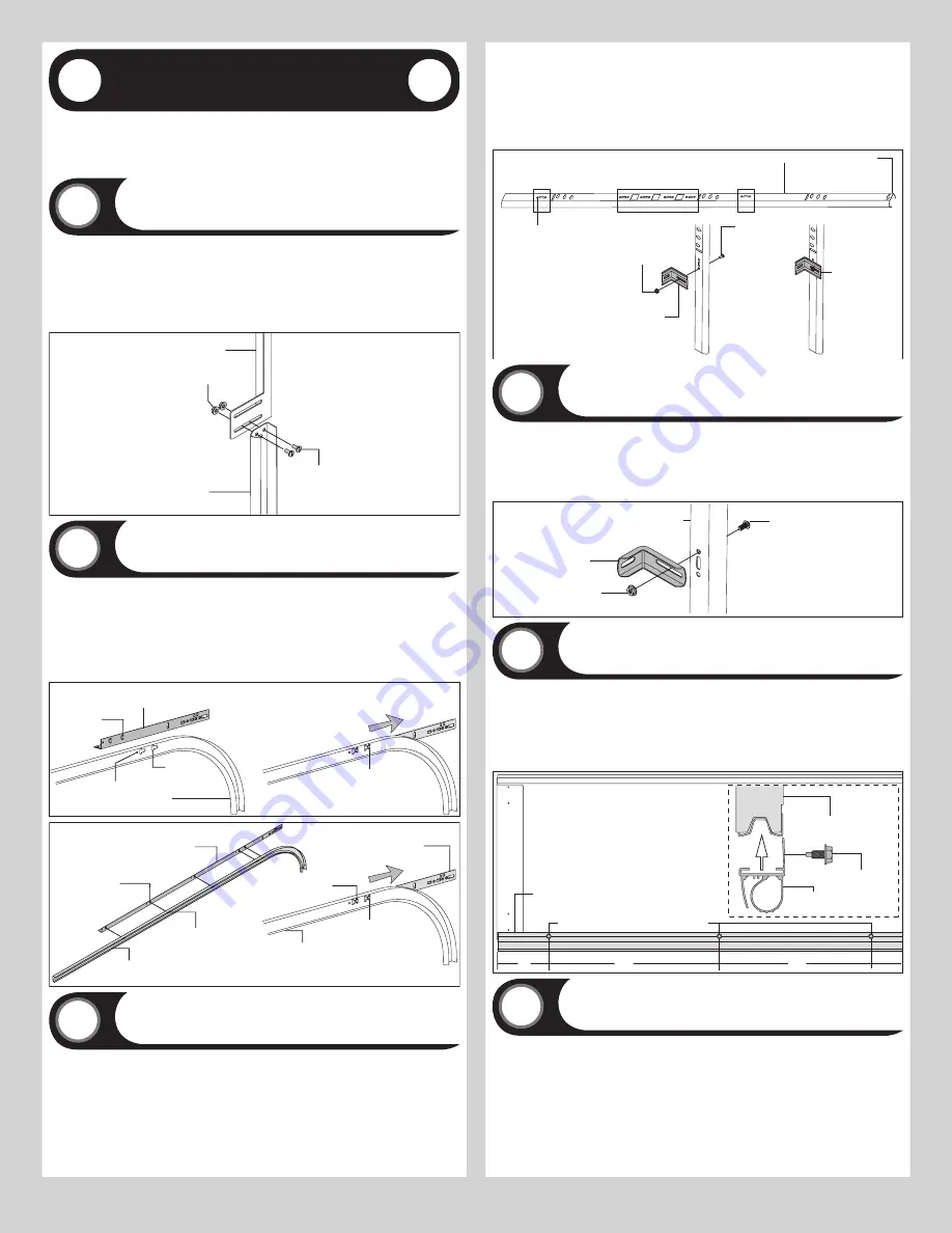
Windload Jamb Brackets
Tools Required: Tape measure, Safety glasses, Leather gloves
4
NOTE:
The following (JB-US’s) denotes a slotted windload jamb bracket.
Measure the length of the vertical tracks. Using the Jamb Bracket Schedule (shown on the
Windload Specification Sheet), determine the placement of the windload jamb brackets for
your door height. Loosely fasten the windload jamb bracket to the vertical track with (1) 1/4”
- 20 x 9/16” track bolt and (1) 1/4” - 20 flange hex nut. Repeat for other side.
Windload
jamb bracket
(1) 1/4”- 20 X 9/16”
Track bolt
(1) 1/4”- 20
Flange hex nut
Vertical track
Bottom Weather Seal
Tools Required: Power drill, 7/16” Socket driver, Tape measure, Safety glasses,
Leather gloves
5
NOTE:
Refer to door section identification, located in the pre-installation section of this
manual.
Determine what size section you need to use for the bottom section. Align the ends of the
bottom weather seal with the bottom of the section and attach with 1/4” - 20 x 7/8” self
drilling screws, one on each end at least 6” from the end of the section and one every 18” in
between.
Bottom section
1/4”-20 x 7/8” Self drilling screws
Bottom section
Bottom
weather seal
6”
18”
18”
1/4”-20 x 7/8”
Self drilling
screws
Bottom
weather seal
Cable Drum Assemblies and Track Rollers
Tools Required: Power drill, 7/16” Socket driver, Tape measure, Safety glasses,
Leather gloves
6
NOTE:
Refer to Package Contents / Parts Breakdown, to determine which bottom corner
brackets you have.
Uncoil the counterbalance lift cables. Depending on which bottom corner brackets you have
(reference illustrations below), slip the loop at the ends of the counterbalance lift cable over
the milford pin of the bottom corner bracket or secure the cable loop to the clevis pin and
bottom corner bracket using a 5/16” flat washer and a cotter pin. Repeat for other bottom
corner bracket.
7
Summary of Contents for 8700
Page 21: ......


