background image

3 of 14

WX-501-0537 • 01.22

The Click 500 series module has two DIP switches on the left side of the module. The DIP switches are used to 

program or reprogram the unit; however, for all Click 512 applications, these DIP switches are unused. 

Note. 

The sixth switch of DIP switch 1 controls the mode of the device. Make sure that this switch is in the OFF 

position. If it gets turned on, the device will enter Program mode and all of the faceplate LEDs will turn off when a 

serial connection is made. To exit Program mode, power will need to be cycled on the device.

Configuration Features

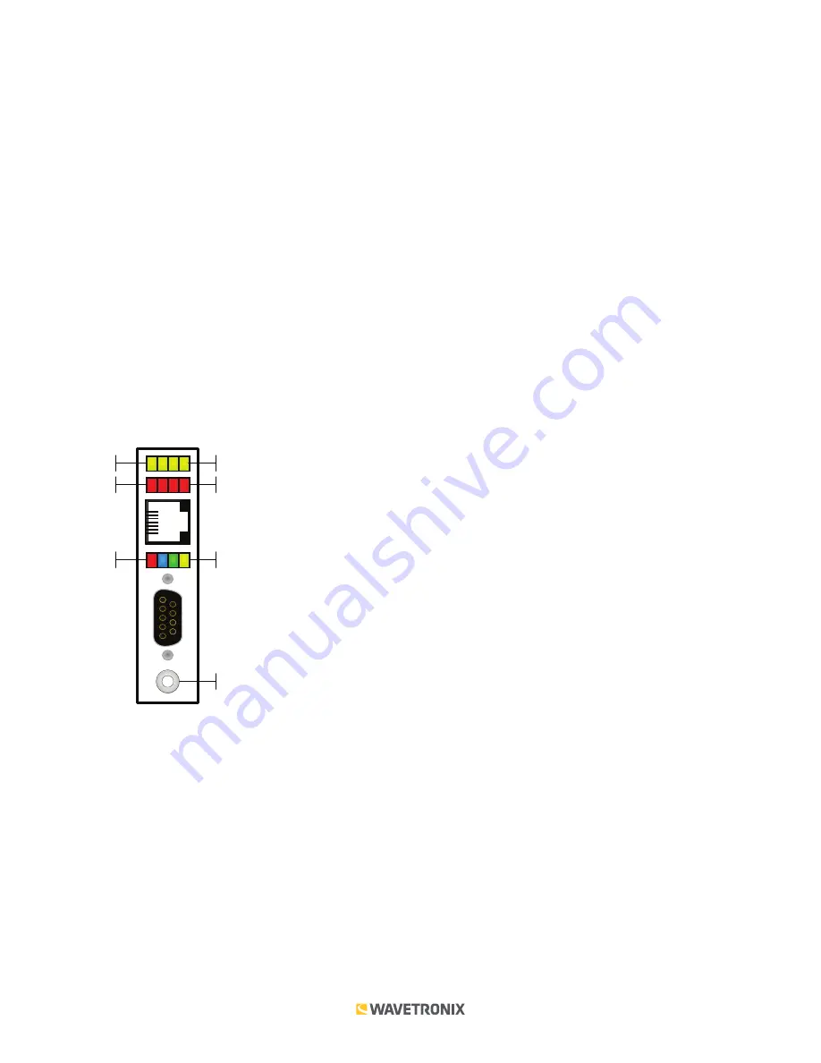
There are three banks of LEDs located on the front of the Click 512.

The yellow and red banks of LEDs display submenu selections and application information. See the Operating 

Modes section of this document for more information.

The system LEDs (multicolored bank in the middle of the module) have dual functions: they are activity indicators, 

reporting system status information, and they are also used in selecting operation modes from the main menu.

The blue LED does not have an activity-indicating function. The other three LEDs indicate system status as follows:


PWR (red) lights up when the device has power.


TD (green) lights up when the device is transmitting data.


RD (yellow) lights up when the device is receiving data.

Sub Menu 1 

Sub Menu 2

Main Menu

Push-button

Yellow LEDs

Red LEDs

Multicolored LEDs

If the Click 512 receives data via one port it will forward (transmit) the data to the other ports. However, only the RD 

(yellow) light will flicker in this case. The TD (green) light is reserved for data originating from the Click 512. 

Located on the front of the module below the DB-9 connector is a push-button labeled 

Mode Switch

. The push-button 

allows you to make selections from the menu. See the Operating Modes section of this document for more information.

Installation

Make sure that the Click 512 is installed on a T-bus with active power and RS-485 communication.

If you are going to use your Click 512 in conjunction with a computer serial port and terminal program, the RS-232 

DB-9 port on the front of the device can be used to make a connection between the Click 512 and the computer.

Obtain the desired serial terminal program and follow the distributor’s instructions to install.

Summary of Contents for Click 512

Page 1: ...s met an alert will trigger through the contact closure and an ASCII string will be transmitted through the DB 9 port A possible application for the Click 512 is to warn specific drivers of a potentia...

Page 2: ...pin 4 from the serial cable to prevent the device from going into Program mode If it enters Program mode all of the faceplate LEDs will turn off and you ll need to power cycle the device The other tw...

Page 3: ...e LED does not have an activity indicating function The other three LEDs indicate system status as follows PWR red lights up when the device has power TD green lights up when the device is transmittin...

Page 4: ...leasing the push button allows you to make a selection in the menu The menu is used to select and run an application s operating modes Select a mode by navigating through the main menu multicolored LE...

Page 5: ...e Click 512 but are only signaled on the attached contact closure device For data verification purposes the event data messages pushed by SmartSensor HD are translated into readable text strings This...

Page 6: ...se motorists in a timely and effective way There are three basic methods to synchronize this trigger Trigger at an ETA to the sign Trigger at a point upstream of the sign Trigger as soon as possible A...

Page 7: ...ETA ms Duration fixed 1 2 3 4 6 5 variable Time to Sign SetbackDistance_ft V_fps 1 Front edge of vehicle enters beam 2 Back edge of vehicle leaves beam The time from point 1 to point 2 is variable and...

Page 8: ...he length and speed of the vehicle 3 Detection event is generated one second after the vehicle leaves the beam This one second delay is fixed 4 Output is activated when front edge of vehicle reaches t...

Page 9: ...ration the device will need to be changed to submode 1 The Click 512 is then configured using the Click Supervisor software See the knowledge base article 0514 Installing and Using Click Supervisor fo...

Page 10: ...e made configuration changes on a driver and saved it to the Click device the word current will appear after that driver to indicate the driver that is currently loaded onto the device Note Changing a...

Page 11: ...er unless another device on the network has the same ID number The Comm subtab allows you to configure how the Click device communicates see the figure and table below Setting Description Baud Rate Al...

Page 12: ...12 tab you will see ten tabs The first is labeled Overall This tab allows you to configure values for the speed and length thresholds see the figure and table below Note Values in Click Supervisor wil...

Page 13: ...d text strings There are nine other tabs you can access They correspond to the eight possible contact closure outputs the Click 512 can be configured to deal with The other eight tabs are labeled O1 t...

Page 14: ...elapse before the activation of the output after the detection If the trigger sync method is Automatic this setting controls the time that will elapse before the activation of the output after the ET...

Reviews: