Wavelength Electronics Laboratory Series User Manual Download Page 20

20

EDIT ADVANCED OPTIONS

Advanced Options can only be edited in Super User mode.

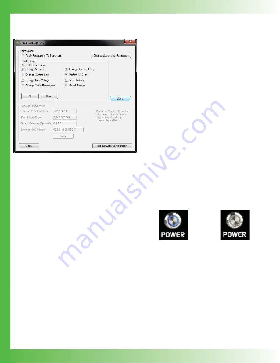
Figure 26.   Advanced Options window

CHANGE PERMISSIONS

Permissions can only be modifi ed in Super User mode and 
apply only to Normal User mode.

1. Under 

Permissions

, select 

Apply Restrictions To 

Instrument

NOTE: To apply the restriction changes to the instrument, 
this checkbox must be selected when the selections are 
saved. 

2.  Select the appropriate checkbox to restrict access to those 

values. Click 

All

 to select all the checkboxes or 

None

 to 

clear them. All restrictions apply to Normal Users when 
the instrument is in Normal User mode or when operated 
in local mode.

3. Click 

Save.

NOTES: 

• Restrictions

 checkboxes can be selected and saved 

without applying the changes to the instrument.

•  To apply the local 

Save Profi le

 and 

Recall Profi le


options to the instrument, the local user 

Save/Modify

 and 

Recall

 checkboxes on the 

Profi le  Editor

 must also be 

checked, as well as the 

Apply Restrictions

 checkbox on 

the 

Advanced Options

 dialog box. 

CHANGE SUPER USER PASSWORD

1. On 

the 

Instrument Operation

 tab, click 

Super User

.

2.  Type the password in the text box and click 

OK

. Select 

the 

Show Password

 checkbox to type the password as 

text. 

3. Under 

Permissions

, click 

Change Super User 

Password

.

4.  Type a new password and then click 

OK

.

CHANGE NETWORK 
CONFIGURATION SETTINGS

Network confi gurations can only be changed in Super User 
mode.

1. Under 

Network Confi gurations

, click 

Edit Network 

Confi guration

.

2.  Type the new information into the text boxes and click 

Save

.

POWER INSTRUMENT ON OR OFF

The front panel can be turned on or off using a remote 
computer.  When the front panel Power button is turned on, 
the button displays a blue circle and the screen displays all 
editable values on the instrument. When it is turned off, the 
screen is black and only the Power button, without the blue 
circle, is available.  This is equivalent to pressing the front 
panel Power button.

• On 

the 

Instrument Operation

 tab, click the 

Power

 button. 

Figure 27.   Power button on

Figure 28.   Power button off

Summary of Contents for Laboratory Series

Page 1: ...oise QCL Instrument QCL1500 LAB 1 5 A Low Noise QCL Instrument QCL2000 LAB 2 0 A Low Noise QCL Instrument NOISESCAN Noise Characterization Scan 55 110014 SMA BNC Cable 55 110015 USB Cable WCB310 Shiel...

Page 2: ...r QCL with this patented1 driver gives you narrow linewidth stable center wavelength and repeatable scans INTUITIVE USER INTERFACE AND SUPERIOR SOFTWARE CONTROL With Wavelength s plug and play instrum...

Page 3: ...ing power To avoid fire hazard use only the specified fuse with the correct type number voltage and current ratings and use only the recommended replacement parts CAUTIONS The QCL instrument has no us...

Page 4: ...Then turn the drawer until the correct voltage label is at the top and replace it in the receptacle Press firmly to make sure the drawer is completely seated It should be flush with the receptacle Fig...

Page 5: ...blue Limit Current value and rotate the Adjustment knob to change to the desired value The instrument will beep when set NOTE The Max Supply Voltage and Cable Resistance values can be ignored for now...

Page 6: ...ground 8 Analog output current monitor 9 Analog monitor ground QCL SMA QCL negative QCL ground Figure 6 SMA Pin Out V Pin 9 QCL or SMA Outer Ring Pin 5 QCL or SMA Center Pin QCL Driver Current Sink QC...

Page 7: ...sec User adjustable EXTERNAL MODULATION MIN TYP MAX UNITS NOTES Modulation Bandwidth 2 3 MHz Sinewave Rise Fall Time 250 200 nsec To full scale Slew Rate 30 V sec Depth of Modulation 90 At 500 kHz Inp...

Page 8: ...tts at idle no output to QCL load GENERAL SPECIFICATIONS VALUE NOTES Warm up Time 1 Hour Remote Interface USB Ethernet Warranty One 1 Year Safety Tested To IEC 61000 3 2 IEC 61000 3 3 IEC 61000 4 2 IE...

Page 9: ...n signal is above the maximum drive current for the laser Over and under voltage protection circuits protect the driver and QCL if the power supply voltages fall outside of the acceptable operating ra...

Page 10: ...cal earth ground 3 QCL SMA SMA connector alternate connection to QCL 4 QCL D SUB 9 Pin female D SUB connector 5 Monitors 9 Pin male D SUB connector 6 USB USB port connection between instrument and a c...

Page 11: ...receptacle Press firmly to make sure the drawer is completely seated It should be flush with the receptacle Figure 11 Fuse Installation and Voltage Selector 5 Close the faceplate again pressing firml...

Page 12: ...ow pulses blue when on Standby and only the back panel power switch is on 2 Adjustment Knob Turn to adjust the numeric values Instrument beeps when values are set 3 Enable Button Allows instrument to...

Page 13: ...aximum Internal Supply Voltage can be lowered to minimize internal instrument temperature or to act as a compliance voltage clamp on the QCL output current See Additional Technical Notes on page 25 fo...

Page 14: ...o the USB flash drive with the filename viscanxx txt where xx starts at 00 and increments 8 To stop mid scan press the red Stop button to abort the scan Any data collected during the aborted scan is s...

Page 15: ...oltage input on this BNC sums with the DC value on the screen The input impedance is 1 k To calculate the external modulation signal voltage see the next section for the transfer function and use the...

Page 16: ...og Setpoint Monitor PIN 6 2 Ground for that measurement is the Analog Monitor Ground PIN 7 or PIN 9 The setpoint monitor and analog current monitor transfer functions depend on the QCL instrument mode...

Page 17: ...rument completely off at both the front and rear panels and then turn it completely on again 2 On the Wavelength website download the ZIP file that is specific to your QCL Laboratory Series model and...

Page 18: ...instrument to the computer and a screen of all editable fields appears The computer screen is editable and the instrument screen is not NOTE One instrument can be controlled remotely at a time Figure...

Page 19: ...ENT PROFILES Profiles can be edited in Super User mode or when Normal Users are not restricted from saving profiles 1 In the Profile Editor Window and in the Available Profiles menu select a profile T...

Page 20: ...also be checked as well as the Apply Restrictions checkbox on the Advanced Options dialog box CHANGE SUPER USER PASSWORD 1 On the Instrument Operation tab click Super User 2 Type the password in the t...

Page 21: ...e button on Figure 31 Enable button off RUN A VI SCAN 1 On the Instrument Operation tab click the green arrow A Specify Data File window opens 2 Navigate to the location to save the scan data name the...

Page 22: ...rument experienced an internal fault See Error Messages on page 24 Switch the back panel power button off and then on again and turn the front panel power button on The internal temperature has reache...

Page 23: ...ser increase the output current limit setting When actively operating in current limit the safety circuits add noise to the output If I run my QCL at about 5 of maximum output current the transfer fun...

Page 24: ...ions The instrument cannot drive current through the load Make sure the QCL SMA or Pins 5 9 of the QCL D SUB are connected A short circuit was detected at the load terminals Please verify the load and...

Page 25: ...p NOTE If you reach 18 V on the MAX Supply Voltage input and the current is still not compliance voltage limited the instrument is operating at its lowest voltage and the voltage limit cannot be reduc...

Page 26: ...L1500 at 1 15 A with 10 Test Load Figure 35 600 kHz Output Plot QCL1500 at 1 15 A with 10 Test Load REMOVE THE BAIL AND FEET FROM AN INSTRUMENT To make sure there is the proper clearance between stack...

Page 27: ...27 MECHANICAL SPECIFICATIONS 0 72 3 89 0 66 16 8 3 92 99 6 6 10 154 9 8 49 215 6 Dimensions are in inches mm Tolerance is 5 8 860 225 0 3 47 88 14 8 860 225 0 16 35 415 16 35 415 17 72 450 3 47 88 14...

Page 28: ...CABLE REGULATIONS European Council Directive 2004 108 EC December 15 2004 on Electromagnetic Compatibility tested to IEC 61000 3 2 and IEC 61000 3 3 IEC 61000 4 2 IEC 61000 4 3 IEC 61000 4 4 IEC 61000...

Page 29: ...CE The information contained in this document is subject to change without notice Wavelength will not be liable for errors contained herein or for incidental or consequential damages in connection wit...

Reviews: