


12
SET UP INTERLOCKS
The Wavelength Interlock Replacement Kit includes a male
D-SUB with the passive interlock pins shorted and a BNC
terminator.
1. For the passive interlock, on the back panel, short PIN 1
and PIN 2 on the QCL D-SUB.
2. For the active interlock, on the back panel, insert a BNC
terminator in the ACTIVE LOCK BNC port.
3. On the front panel, the key switch must be on UNLOCK to
enable the current to the QCL.
NOTE: To disable operation, turn the key switch to the
LOCKED position. The key can only be removed when in the
locked position.
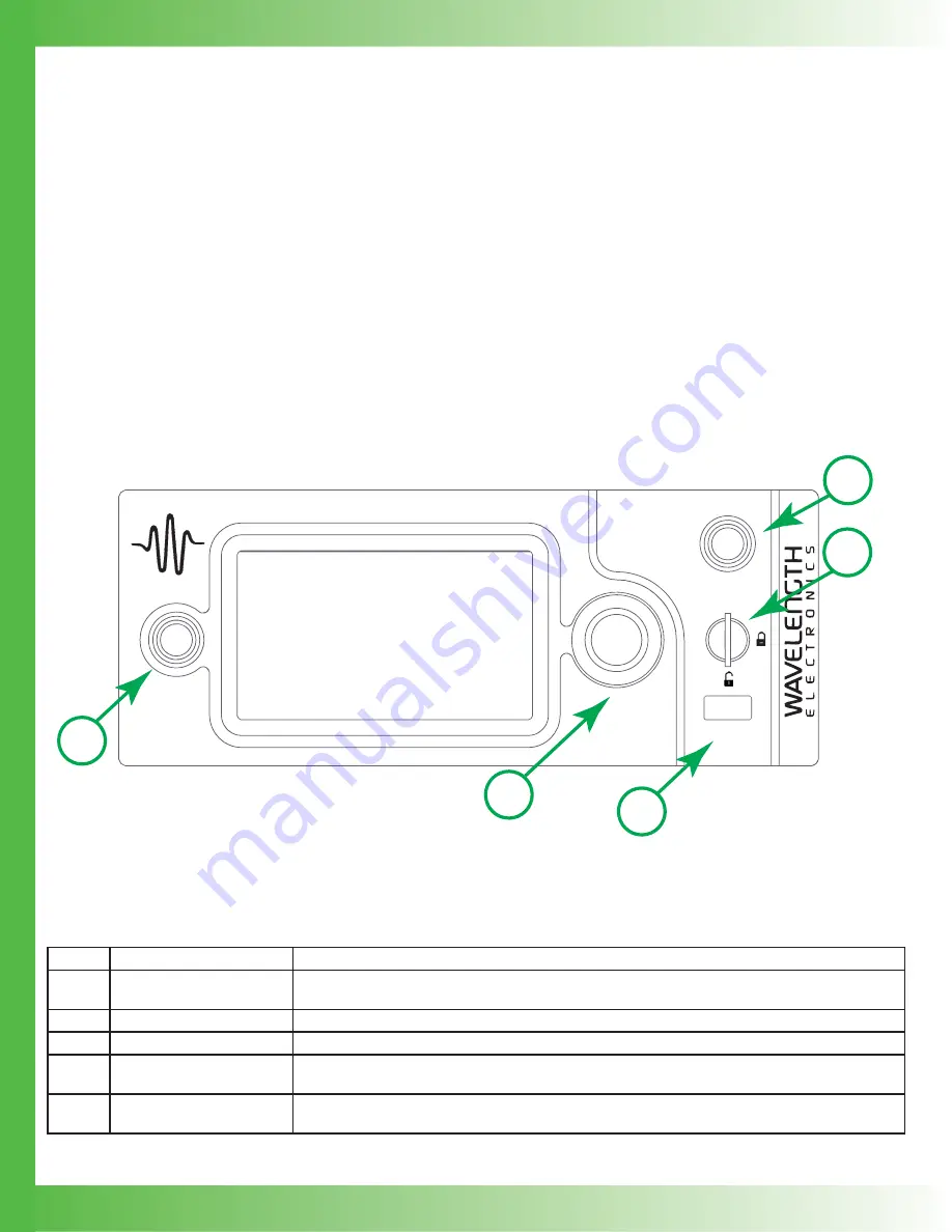
FRONT PANEL
QCL1000
LAB
ENABLE
DATA
POWER
1
5
3
2
4
Figure 14.
Front Panel
Table 4.
Table 5.
Front Panel Functions
NAME
DESCRIPTION
1
Power Button
Powers the application electronics. Glows blue when application electronics power is on and unit
is operational, slow pulses blue when on Standby and only the back panel power switch is on.
2
Adjustment Knob
Turn to adjust the numeric values. Instrument beeps when values are set.
3
Enable Button
Allows instrument to deliver current to the QCL. Glows blue when current is enabled.
4
Keylock Switch
UNLOCK allows laser output current to fl ow, LOCK disables laser output current. NOTE: The
key can be removed only in LOCK position.
5
Data Port
USB fl ash drive, used to update the fi rmware or save data. This is not used for remote USB
control of the instrument.
TEXT AND ICON COLOR KEY
TEXT
Text indicates current state.
White, Green
Uneditable
fi eld, for information only.
Blue
Editable fi eld, touch to select or toggle fi eld
(text highlights and changes color), adjust
using either the touchscreen or adjustment
knob. Instrument beeps and text returns to
blue when values are set. Touch again to
cancel selection.
ICONS
Icon color indicates current state.
Blue
Screen is active.
Grey
Screen is inactive, touch icon to access that screen.


