WM_PRJ_Q2400_PTS_005 -007
18th January 2006
Confidential©
All rights reserved
Page:
27
/
51
This document is the sole and exclusive property of WAVECOM. Not to be
distributed or divulged without prior written agreement.
A/ Differential connection
Impedance of the microphone input in differential mode:
•
Module ON: R
in
= 10 k
Ω
+/-10 %
•
Module OFF: R
in
>1 M
Ω
+/-10 %
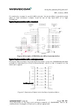
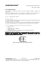
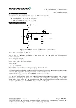
Typical implementation:
L1
L2
C1 C2
C4
C3
MIC1P
MIC1N
VCC
C5
R1
R2
R3
R4
Figure 14: MIC1 inputs (differential connection)
R1 = R4 = from 100 to 330
Ω
.
R2 = R3 = usually between 1 k
Ω
and 3.3 k
Ω
as per the microphone
characteristics.
C1 = 33 pF to 47 pF.
C2 = C3 = C4 = 47 F to 100 pF.
C5 = 47 µF.
L1 = L2 = 100 nH.
R1 and R4 are used as a voltage supply filter with C5.
C1 has to be the nearest possible to the microphone. Microphone manufacturers
provide this capacitor directly soldered on the microphone.
C2 has to be very close to the WISMO module connector.
L1, L2, C3 and C4 has to be put near the WISMO module connector and can be
removed according to their environment (ground plane, shielding ...etc). The
best way is to plan all the components and to remove those which are not
necessary to filter out the TDMA noise on the audio path.


