


WM_PRJ_Q2400_PTS_005 -007
18th January 2006
Confidential©
All rights reserved
Page:
12
/
51
This document is the sole and exclusive property of WAVECOM. Not to be
distributed or divulged without prior written agreement.
Power Supply Voltage
V
MIN
V
NOM
V
MAX
VBATT
3.3 V (*)
3.6 V
4.5 V (**)
VDD
3.1 V
4.5 V
Table 1: Power supply voltage
(*): This value has to be guaranteed during the burst (with 2.0 A Peak in GSM or
GPRS mode).
(**): max operating Voltage Stationary Wave Ratio (VSWR) 2:1.
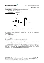
When the module is supplied with a battery, the total impedance
(cprotPCB) should be < 150 m
Ω
to limit voltage drop-
out within emission burst.
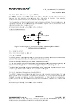
As the radio power amplifier is directly connected to VBATT, the module is
sensitive to any Alternative Current on lines. When a DC/DC converter is used,
Wavecom recommends to set the converter frequency in such a way that the
resulting voltage does not exceed the values in following table and Figure 2.
Freq.
(kHz)
U
ripp
Max
(mVpp)
Freq.
(kHz)
U
ripp
Max
(mVpp)
Freq.
(kHz)
U
ripp
Max
(mVpp)
<100 50 800 4 1500 34
200 15.5 900 15.2 1600 33
300 6.8 1000 9.5 1700 37
400 3.9 1100 32 1800 40
500 4 1200
22
>1900
40
600 2 1300
29
700 8.2 1400 30
Table 2: Maximum voltage ripple (Uripp) vs Frequency in GSM & DCS


