


1. Install the power pack according to its instructions.
2. Connect the power pack wires to the sensor as follows:
RED wire (+24VDC) to the +24V IN terminal on the sensor.
BLACK wire (Return) to common (COMM.) terminal on the sensor.
BLUE wire to control output (CTRL. OUT) terminal on the sensor.
3. Wire the Isolated Relay. The Isolated Relay is rated for 1A @ 30VAC/VDC.
Connect the wires necessary to the application that requires this output:
Normally Closed (N.C.) - Open when occupancy is detected.
Relay Common (must be used for proper operation)
Normally Open (N.O.) - Closed when occupancy is detected.
The bottom terminal on the sensor is not used.
4. Turn the power on.
5. Test and adjust the sensor if necessary.
6. Install industry standard decorator wall switch cover plate (not included).
INSTALLATION
WARNING
TURN THE POWER OFF AT THE CIRCUIT BREAKER
BEFORE INSTALLING POWER PACKS OR SENSORS.
!
Visit our website for FAQs: www.wattstopper.com
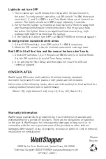
PW-100-24 Wiring
Common
White (Neutral)
Red
(Load)
Red (Line)
White
Black
Hot
Neutral
Power
Pack
Blue
Blac
k
Red
Lighting
Load
Control Outputs
+24 VDC
Isolated Relay Outputs
Normally closed contact
Common
Normally open contact
Not used


