background image

6

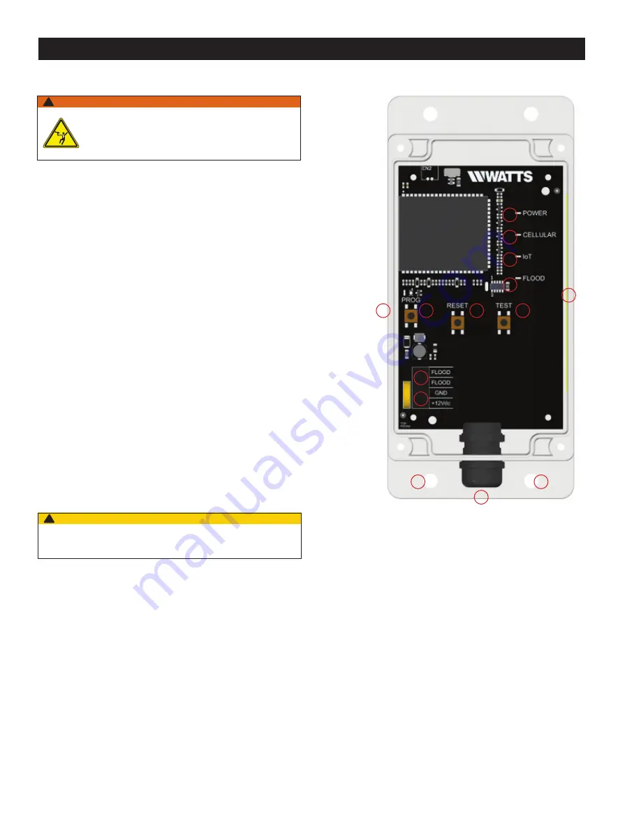
1.    Identify preferred location for mounting Wireless Node. The 

Wireless Node must be located away from large metal com-

ponents and structures that may block the cellular signal. In 

addition, the cellular antenna is located on the inner sidewall 

of the enclosure (11). When mounting, ensure that this side 

of the device is away from any walls, wires, pipes, or other 

obstructions, especially anything metallic.

2.    Before mounting, plug in the Wireless Node to ensure that 

a connection can be made in the preferred location. Once 

plugged in, the device will automatically go through a start-

up process. A cellular connection has been made if, after the 

start-up process, the Cellular LED (8) is a steady blue. If it is 

blinking, there is a poor connection, and if it is off, there is 

no connection. If there is a poor or no connection, identify a 

new location for mounting.

3.    Unplug the Wireless Node from the power supply.
4.    Mount the Wireless Node in the identified location using the 

four 0.27" diameter mounting holes (13). Screws are not 

included.

5.    Route wires from terminals 7 and 8 of the Junction Box 

through the wiring gland (12) and connect to the Wireless 

Node at the "Flood" screw terminal (2). Polarity does not 

matter. Six feet of wire is supplied with the unit, but the 

Wireless Node can be located up to 100 feet away from 

the Junction Box. If additional wire is used. it must meet the 

required rating for the Junction Box (300V, 16-24 AWG).

6.    Route wires for included 12VDC power supply through the 

wiring gland (12) and connect to the Wireless Node at the 

appropriate screw terminal (1). Polarity must be correct or 

the Wireless Node will not operate. 

7.    Tighten the wiring gland (12) to prevent water or dust from 

entering the Wireless Node.

8.    Connect the power supply to the Wireless Node and 

Junction Box.

Installing the Wireless Node 

1

7

2

8

3

9

4

10

5

11

13

6

12

13

Use only the provided power supply as other power supplies may not 

meet the rating and specifications for this device.

CAUTION

!

Installation and Operation

WARNING

!

Ensure all power supply to the Wireless Node is turned 

off before making any connections to the Wireless Node. 

Failure to do so may result in electrocution, personal 

injury, and/or death.

Summary of Contents for SentryPlus 113RFP

Page 1: ... Required Tools and Materials for Installation 2 Installation and Operation 3 ISolenoid Operation For Existing LFF113RFP Installations Only 3 Installing the Flow Sensor Backflow Upgrade Kit Only 3 Wiring Retrofitting the junction box 4 Installing the Wireless Node 6 Registering Your Device and Alert Configuration 7 Start up Instructions 8 Warranty 8 Read this Manual BEFORE using this equipment Fai...

Page 2: ...ctorial and or safety mes sage to identify hazards and alert you to the potential for death or serious personal injury Identifies hazards which if not avoided will result in death or serious injury Identifies hazards which if not avoided could result in death or serious injury Identifies hazards which if not avoided could result in minor or moderate injury Identifies practices actions or failure t...

Page 3: ... Flow Sensor is installed in the discharge piping from the RPZ relief valve If the Flow Sensor senses water in the dis charge piping it will signal the Junction Box to close the valve Installation Notes 1 Install the supplied tee for the Flow Sensor in the RPZ dis charge line in the HORIZONTAL position as shown below 2 Cut Sensor Probes to length The ends of the Sensor Probes should be located bet...

Page 4: ...tection or protection NOTICE Wiring the Junction Box For Existing LFF113RFP Installations Only After removal of power from the circuit disengage the wiring from o Main terminals inside Junction Box o Terminals 1 and 2 Flow Sensor o Terminals 3 and 4 Solenoid o Terminals 5 and 6 remote trip indicator if wired Remove the Junction Box from the ACV or wall mount Replace the Junction Box with the new u...

Page 5: ...is adjust able from 0 seconds to over 1 hour Adjust the time delay by using the delay adjustment dial in the Junction Box Use a small Phillips head screwdriver to adjust either the range selector 0 6 0 12 0 30 0 60 on the left side or the unit selector 0 1 sec sec min hr on the right side Increase the time delay by adjusting the dial clockwise decrease the time delay by adjusting the time delay co...

Page 6: ...oles 13 Screws are not included 5 Route wires from terminals 7 and 8 of the Junction Box through the wiring gland 12 and connect to the Wireless Node at the Flood screw terminal 2 Polarity does not matter Six feet of wire is supplied with the unit but the Wireless Node can be located up to 100 feet away from the Junction Box If additional wire is used it must meet the required rating for the Junct...

Page 7: ...ess Node is connecting to the Cloud Once a Cloud connection is established the Program button light will blink rapidly for a few seconds and then shut off The Cellular LED 8 and IoT LED 9 should both be a solid blue 2 Cellular Connection Once the start up sequence is completed the Cellular LED will be a steady blue if there is a good connection It will blink if there is a poor connection There wil...

Page 8: ... have other rights that vary from State to State You should consult applicable state laws to determine your rights SO FAR AS IS CONSISTENT WITH APPLICABLE STATE LAW ANY IMPLIED WARRANTIES THAT MAY NOT BE DISCLAIMED INCLUDING THE IMPLIED WARRANTIES OF MERCHANTABILITY AND FITNESS FOR A PARTICULAR PURPOSE ARE LIMITED IN DURATION TO ONE YEAR FROM THE DATE OF ORIGINAL SHIPMENT IOM UPGRADEKIT SentryPlus...

Reviews: