background image

7

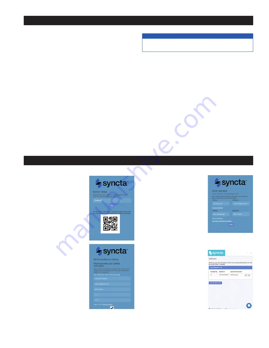
1.   Using a smart phone or tablet, 

scan the QR code on the side 

on the Wireless Node, or go to 

https://connected.syncta.com.

2.   When prompted, enter the 

Device ID. The Device ID is a 

15-digit number found beneath 

the QR code on the side of the 

Wireless Node.

3.   Follow onscreen prompts to 

create a Syncta account, or 

if you are an existing Syncta 

user, log in to your account. 

The device can be registered 

to multiple accounts.

4.   Once the device is regis-

tered to your account, follow 

prompts to add notifications.


 To manage alerts, login to your 

account on Syncta.com.  

Wireless Node Operation

1.  

Start-Up

 – Upon start-up, the Power LED (7) will light up 

a steady green to indicate power is supplied. The Wireless 

Node will automatically go into its start-up sequence. During 

the start-up sequence, the light over the Program button 

(5) will begin as solid white and then change to a blinking 

green, indicating the Wireless Node is searching for a cellu-

lar connection. Once a cellular connection is established, the 

Program button light will start blinking cyan, indicating that 

the Wireless Node is connecting to the Cloud. Once a Cloud 

connection is established, the Program button light will blink 

rapidly for a few seconds, and then shut off. The Cellular 

LED (8) and IoT LED (9) should both be a solid blue.

2.  

Cellular Connection

 – Once the start-up sequence is 

completed, the Cellular LED will be a steady blue if there is 

a good connection. It will blink if there is a poor connection. 

There will be no color if there is no connection.

3. 

 IoT  Connection

 – If there is a Cloud connection, the IoT 

LED will be a steady blue. There will be no color if it is off.

NOTICE

If there is no Cloud connection, then notifications will not be 

sent to the user via Syncta.

4.  

Flood LED 

– If a flood event occurs, the Flood LED (10) 

will be a steady orange. It will remain on so long as there 

is a flood condition.

5.  

Test Button

 – When Cellular and Cloud connections 

have been made, a test message can be sent through the 

Syncta app by pressing the Test Button (3).

6.  

Reset Button

 – You can reset the Wireless Node and 

restart the start-up sequence by pressing the Reset but-

ton (4).  This will cause all on-going operations to cease.

7. 

 Program  Button

 – The Program button (5) should not be 

pressed and is for factory use only.

Installation and Operation

Registering Your Device and Alert Confi guration

Summary of Contents for SentryPlus 113RFP

Page 1: ... Required Tools and Materials for Installation 2 Installation and Operation 3 ISolenoid Operation For Existing LFF113RFP Installations Only 3 Installing the Flow Sensor Backflow Upgrade Kit Only 3 Wiring Retrofitting the junction box 4 Installing the Wireless Node 6 Registering Your Device and Alert Configuration 7 Start up Instructions 8 Warranty 8 Read this Manual BEFORE using this equipment Fai...

Page 2: ...ctorial and or safety mes sage to identify hazards and alert you to the potential for death or serious personal injury Identifies hazards which if not avoided will result in death or serious injury Identifies hazards which if not avoided could result in death or serious injury Identifies hazards which if not avoided could result in minor or moderate injury Identifies practices actions or failure t...

Page 3: ... Flow Sensor is installed in the discharge piping from the RPZ relief valve If the Flow Sensor senses water in the dis charge piping it will signal the Junction Box to close the valve Installation Notes 1 Install the supplied tee for the Flow Sensor in the RPZ dis charge line in the HORIZONTAL position as shown below 2 Cut Sensor Probes to length The ends of the Sensor Probes should be located bet...

Page 4: ...tection or protection NOTICE Wiring the Junction Box For Existing LFF113RFP Installations Only After removal of power from the circuit disengage the wiring from o Main terminals inside Junction Box o Terminals 1 and 2 Flow Sensor o Terminals 3 and 4 Solenoid o Terminals 5 and 6 remote trip indicator if wired Remove the Junction Box from the ACV or wall mount Replace the Junction Box with the new u...

Page 5: ...is adjust able from 0 seconds to over 1 hour Adjust the time delay by using the delay adjustment dial in the Junction Box Use a small Phillips head screwdriver to adjust either the range selector 0 6 0 12 0 30 0 60 on the left side or the unit selector 0 1 sec sec min hr on the right side Increase the time delay by adjusting the dial clockwise decrease the time delay by adjusting the time delay co...

Page 6: ...oles 13 Screws are not included 5 Route wires from terminals 7 and 8 of the Junction Box through the wiring gland 12 and connect to the Wireless Node at the Flood screw terminal 2 Polarity does not matter Six feet of wire is supplied with the unit but the Wireless Node can be located up to 100 feet away from the Junction Box If additional wire is used it must meet the required rating for the Junct...

Page 7: ...ess Node is connecting to the Cloud Once a Cloud connection is established the Program button light will blink rapidly for a few seconds and then shut off The Cellular LED 8 and IoT LED 9 should both be a solid blue 2 Cellular Connection Once the start up sequence is completed the Cellular LED will be a steady blue if there is a good connection It will blink if there is a poor connection There wil...

Page 8: ... have other rights that vary from State to State You should consult applicable state laws to determine your rights SO FAR AS IS CONSISTENT WITH APPLICABLE STATE LAW ANY IMPLIED WARRANTIES THAT MAY NOT BE DISCLAIMED INCLUDING THE IMPLIED WARRANTIES OF MERCHANTABILITY AND FITNESS FOR A PARTICULAR PURPOSE ARE LIMITED IN DURATION TO ONE YEAR FROM THE DATE OF ORIGINAL SHIPMENT IOM UPGRADEKIT SentryPlus...

Reviews: