7
4.2 Plumbing and Air Connections
To avoid injury, death, fire, explosion, leak, or property damage:
• The fluid waste from the drain connection MUST NEVER
BE reintroduced into the incoming water stream. HF
scientific recommends that operators review with local
authorities concerning the proper disposal of waste
diluted fluids.
• All plumbing connections MUST BE made through the
provided stainless steel connections. Fittings should not
be modified or substituted.
• The air line and the water line MUST NOT BE reversed
in connecting the supplies. Connecting the water source
to the air line will damage the electronics and void
the warranty.
• All connections MUST BE properly installed and sealed
to ensure water tightness and preserve the ratings of
the instrument.
• The drain MUST BE open to the atmosphere for proper
operation. Ensure the vent drain remains open and is not
subject to fouling.
All wet and air connections are made with user supplied tubing using
the compression fittings attached to the SSR-Ex. When using the
compression fittings, follow these steps:
Step 1: Unscrew the nut from the applicable connection point.
Step 2: Remove the nut, front sleeve, and back sleeve from the
SSR-Ex.
Step 3: Place the nut, then the back sleeve, and then the front sleeve
onto the applicable tubing.
Step 4: Slide the tubing into the open connection point and
tighten the nut to secure the tubing. Refer to Figure 9.
Fitting Connections for assistance to assemble the tubing
connection. Refer to Figure 10 - Utility Connections for
assistance locating the proper fitting connection on the
enclosure for the sample to be connected.
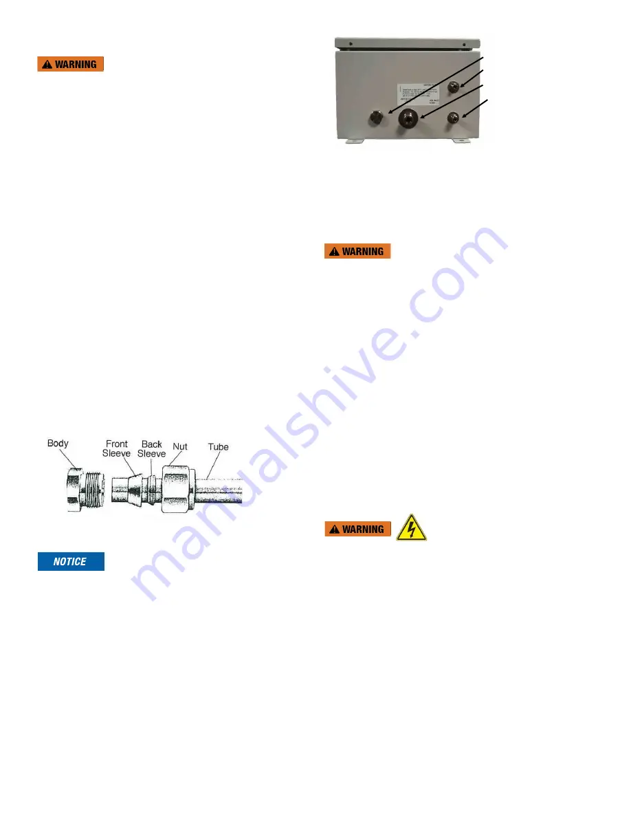
Figure 9 - Compression Fitting
When making the plumbing connections, be advised that:
• The maximum pressure for proper operation is 3 bar (45 PSI).
• The maximum sample water intake and drainage flow is
150 ml/minute.
• The maximum allowable fluid temperature is 55°C (131°F).
• The sample water supply does not need to be pressurized.
The SSR-Ex incorporates a pressure regulator at the water
supply inlet.
• In order to ensure that the sample measured is representative of
the ballast water, keep sample pipe runs as short as possible.
• A water shut off valve should be located close to the instrument
to allow for periodic maintenance.
• An air shut off valve should be located close to the instrument to
allow for periodic maintenance.
EMERGENCY DRAIN (NO CONNECTION
NEEDED)
SAMPLE WATER (6mm connection)
MAIN DRAIN (12 mm connection)
PURGE AIR (AIR ONLY 6mm
connection)
NOTE: IMAGE DEPICTS BOTTOM OF
THE ENCLOSURE.
DO NOT MIX UP THE AIR and WATER
CONNECTIONS. INSTALLING THE
WATER INTO THE AIR CONNECTION
WILL VOID THE WARRANTY.
Figure 10 - Utility Connections
All wet and air connections are made with user supplied OD tubing
using the compression fittings attached to the SSR-Ex. All air and water
tubing connected to the instrument is to be supplied by others. When
using the compression fittings, see Figure 9 - Compression Fitting and
then follow these steps:
Do not connect sample water line to the purge air connection.
Plumbing Connections
Step 1: Connect the sample water line to the SSR-Ex using the 6 mm
OD fitting on the bottom of the enclosure. Reference Figure
10 - Utility Connections.
Step 2: Connect the main drain line to the SSR-Ex using the 12 mm
OD fitting on the bottom of the enclosure.
Reference Figure 10 - Utility Connections. There is no tubing
connection for the emergency drain.
Air Connection
Step 1: Install the air/filter dryer assembly by mounting it in
a convenient location near the SSR-Ex between the
compressed air supply and the SSR-Ex.
Step 2: Connect the compressed air supply to the air/filter dryer
assembly intake.
Step 3: Connect the air supply tubing from the air/filter dryer
assembly output to the SSR-Ex using the 6 mm OD fitting
on the bottom of the enclosure. Reference Figure 10 - Utility
Connections.
4.3 Electrical Connections
The power must be provided by a safe remote location. All
power must be removed from a safe location while the electrical
compartment access is open. Do not reconnect power until the
electrical compartment access is closed and all captive Philips
screws have been replaced and tightened appropriately.
All electrical connections are located in the upper electrical
compartment. The electrical compartment access at the front
can and should only be opened during installation. No power
should be applied until the electrical compartment access is
closed and sealed.
The SSR-Ex has two types of electrical connections. First, the mains
power connection, which connects to the Air Sentinel II through the
cable gland on the left side of the SSR-Ex. Second, the low voltage
connections, which are made through the cable glands on the right
side of the SSR-Ex.


