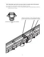
FIG. A
3.5 Turn the catch basin over and set to appropriate line and grade per the
construction plans.
3.6 If a catch basin is not used, pipe connections are made to the bottom of the
channel, or to an end cap. Drill through the molded pipe hub with a 4" hole
saw or reciprocating saw, taking care not to rake the inside wall of the hub.
Make No Hub pipe connections with a suitable coupling (by others).
4. Layout
4.1 Refer to the installation diagram.
4.2 Working from the deepest outlet connection(s) back upstream, lay the trench
drain sections alongside the open trench per the labels on each section and
the installation diagram.
4.3 Each channel and frame section is also marked with arrows, indicating the
direction of flow. Confirm they are all pointing per the flow shown on the
installation diagram.
5. Rebar Anchoring & Leveling of Sections
5.1 Establish accurate line and grade reference and control using your preferred
method-e.g. string line, laser level, etc.
5.2 Starting from the outlet or catch basin, set the first structural frame and channel
section shown on the installation diagram on the desired control line along the
excavated trench.
2
3. Catch Basins & Piping Connections
3.1 Catch basins, if used, should be set first. If no catch basin is used
skip to step 3.6.
3.2 Using a reciprocating or hole saw, remove the circular pipe connection cutout(s)
where the basin will connect to discharge piping.
3.3 Invert the catch basin on a flat surface, and butt the section(s) shown on the
installation drawing against the pattern on the basin. Use a reciprocating saw
to remove the cutout on the basin.
3.4 With the cutout correctly removed, the channel tongue should slide inside the
hole in the basin, with the channel flange flush against basin's exterior wall (Fig. A).
Summary of Contents for Dead Level Series
Page 11: ...Notes...
Page 23: ...Notas...


