background image

4

IOM-A-Deringer 40/40X/50/50X_6-8


   2005 

EDP#2916006


© 2020 Watts

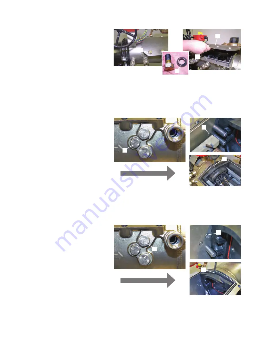
Removing Access Port Cover Plate

C

D

1.   Using  a 

15

/

16

" socket wrench loosen all eight bolts 

on the access port cover plate (A). 

2.   Remove bolts and tapered washers (B) and store in 

a safe place. Be careful not to lose tapered washers 

as the access cover will not seal properly without 

the tapered washers.

3.   Remove access port cover plate (C). Do not remove 

access port O-ring (D).

A

B

Removing the First Dual-action

TM

 Check Module

FLOW

C

A

1.   Use  a 

15

/

16

" socket wrench to loosen the check 

retainer bolts on both sides of the valve body (A). 

Do not completely remove check retainer bolts from 

valve body. Loosen the bolts until the ends of the 

bolts are flush with the inner wall of the valve body 

(B).

2.   Insert a flathead screwdriver between the inner valve 

body and the first check module flange (C), gently 

push the first check module in the downstream 

direction until the first check module can easily be 

removed from the access port by hand.

B

Removing the Second Dual-action Check Module

1.   Use a 1

1

/

8

" socket wrench to loosen the check retainer 

bolts on each side of the valve body (A). Do not  

completely remove check retainer bolts from valve 

body. Loosen the bolts until the ends of the bolts are 

flush with the inner wall of the valve body (B).

2.   Insert a flathead screwdriver between the inner valve 

body and the second check module flange (C),  

gently push the second check module in the  

upstream direction until the second check module  

can easily be removed from the access port by hand.

FLOW

C

B

A

Summary of Contents for AMES Deringer 40

Page 1: ...and follow all safety and use information can result in death serious personal injury property damage or damage to the equipment Keep this manual for future reference You are required to consult the l...

Page 2: ...ool can be used For example allen wrenches instead of allen drive sockets Tools Required 15 16 Socket 11 8 Socket Wood Block 2 x 4 x 5 Wood Block 1 x 2 x 16 2 Phillips Head Screwdriver 2 Flathead Scre...

Page 3: ...cks water will be released Take precautions to ensure discharging water does not damage the surrounding area equipment or create an unsafe condition 1 DO NOT OPEN Main test cock number 1 as it is stil...

Page 4: ...til the ends of the bolts are flush with the inner wall of the valve body B 2 Insert a flathead screwdriver between the inner valve body and the first check module flange C gently push the first check...

Page 5: ...damage or fouling to the sealing seat Do not remove unless the seat cage is being replaced 6 Reverse the order of above instructions to reassemble bypass check valve A Part 2 1 To replace a damaged r...

Page 6: ...l gaskets F before threading meter coupling nuts into place B C E E G F E FLOW D A Maintenance of First True Seal Check Module 1 Use a 2 phillips head screwdriver to remove tower screws A from the fir...

Page 7: ...lastomer disk D When replacing elastomer disk D be certain that no air water or debris is trapped in the clapper H cavity behind the elastomer disk D 4 Reverse the order of the above instructions to r...

Page 8: ...e backside of the second check seat ring G Using a 1 x4 piece of wood cut to 16 length H as a lever between access port wall the 2 x4 F gently move the second check module A into its fully seated posi...

Page 9: ...k retaining screws I The first check module must be fully seated to ensure retainer screws do not bind against check towers Binding retainer screws against check towers will result in permanent damage...

Page 10: ...D D Maintenance of Relief Valve continued B D 1 Check the rubber seal on the relief valve piston assembly A for fouling or damage by making sure the indentation of the seat in the rubber seal is pres...

Page 11: ...B making sure the diaphragm lays flush on the bottom of the piston assembly with no wrinkles or tears in the diaphragm 2 Place the relief valve spring C back onto the relief valve assembly A and slide...

Page 12: ...the pitot tube B at the top of the pitot tube must face directly UPSTREAM toward the 1 shutoff valve Proper orientation can be confirmed visually by removing the main line valve cover and first check...

Page 13: ...certain that access port O ring A does not become dislodged during the process 3 Insert cover bolts D and tapered washers E flat side facing up into tapered cover holes F Tapered washers E must be pr...

Page 14: ...screwdriver close bypass test cock number 1 and 2 B Test cock is closed when screwdriver slot on stem is perpendicular to water flow through test cock 3 Use the T handles to open bypass ball valve nu...

Page 15: ...A counterclockwise to the open position Shutoff valve is open when yellow orange position indicator flags are parallel to the mainline water flow 2 Slowly rotate the number 2 shutoff valve operation h...

Page 16: ...ranty shall be invalidated by any abuse misuse misapplication improper installation or improper maintenance or alteration of the product Some States do not allow limitations on how long an implied war...

Reviews: