10
IOM-A-Deringer 40/40X/50/50X_6-8
2005
EDP#2916006
© 2020 Watts
Maintenance of Relief Valve
B
A
E
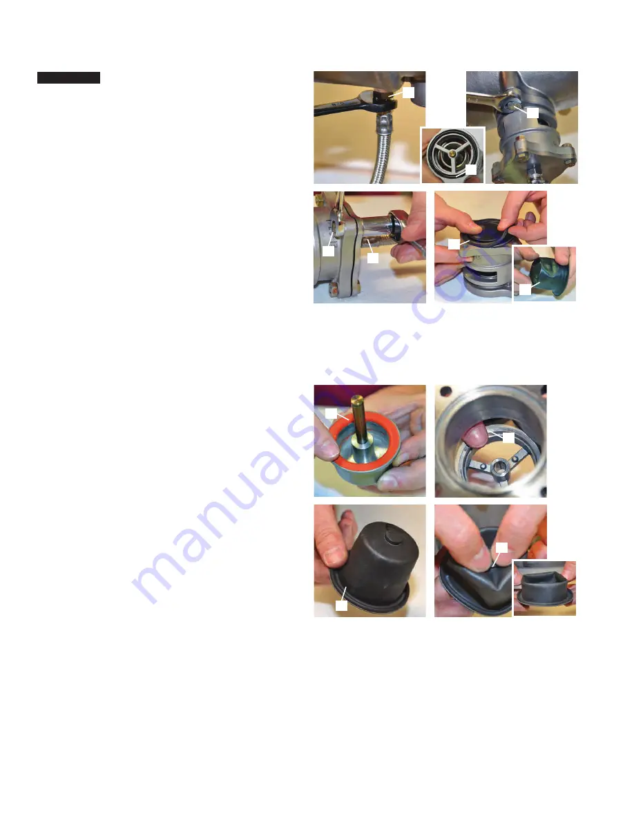
1. Using a
5
/
8
" box wrench disconnect the relief valve sensing
line from the valve body (A).
2. To remove the relief valve from the valve body disconnect
the two relief valve mounting bolts (B) using a
9
/
16
" wrench.
When removing the relief valve be sure not to drop the top
O-ring (C) as the relief valve body uses this O-ring to seal
against the valve body.
3. To access the relief valve remove the relief valve cover using
two
7
/
16
" wrenches to remove cover bolts (D).
4. Remove the relief valve diaphragm (E) and check the
diaphragm for tears, holes or debris (F).
C
NOTICE
If one is certain that the relief valve requires maintenance proceed as follows.
F
D
D
Maintenance of Relief Valve (continued)
B
D
1. Check the rubber seal on the relief valve piston assembly (A) for
fouling or damage by making sure the indentation of the seat in
the rubber seal is present all the way around. (Confirm the relief
valve piston assembly (A) sets flush on relief valve seat (B).
2. Check relief valve seat (B) for fouling or damage before
reinstalling the relief valve piston assembly (A).
3. Once the relief valve is ready to be reassembled, the first step is
to reform and reattach the diaphragm to the piston.
4. Move the diagram (C) to the fully open position making sure the
embossed center is facing up.
5. While holding the diaphragm (C) with both hands, use your
thumbs to gently push down on embossed center (D) so the
diaphragm collapses into itself and forms a circle so that the
bottom of the piston assembly can be inserted into the
diaphragm and the embossed center can be pushed into
the piston assembly groove.
C
A


