


Ufly Controller and BCM for Modulex EXT
CHAPTER 6: BOILER COMMUNICATIONS MODULE (BCM)
OMM-0159_A_A
• 6/28/2022 Technical Support • (800) 526-0288 • Mon-Fri, 8 am - 5 pm EST Page
54
of
83
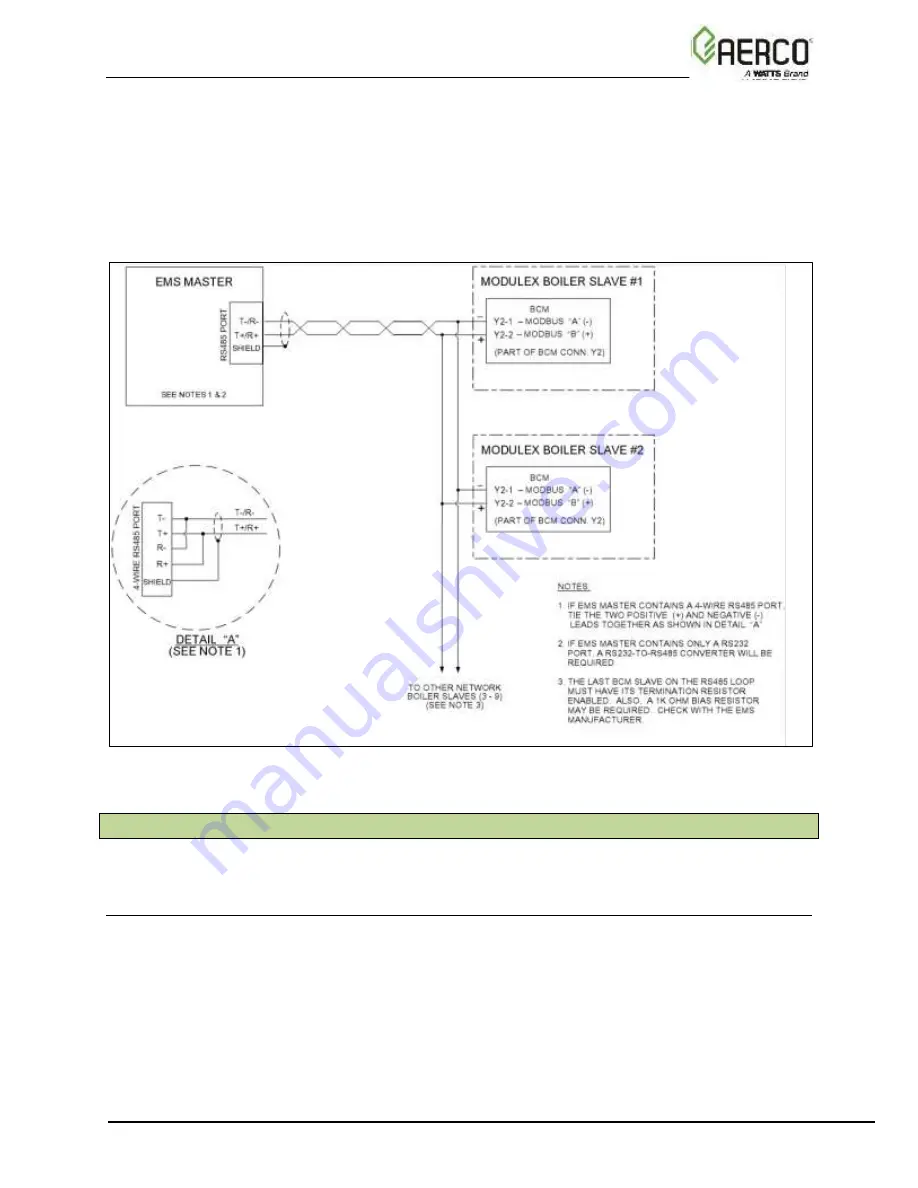
Figure 6-15 shows a Sample Modbus Network wiring diagram for a Master EMS/BAS controlling
BCM Controller Slaves. This Figure shows an EMS or BAS Master equipped with a RS485 port.
If the EMS or BAS contains a 4-
Wire RS485 port, refer to Detail “A” for wiring details. If the
controlling Master EMS/BAS contains only a RS232 port, a RS232-to-RS485 converter will be
required to interface with connector Y2 at each BCM Controller. It should be noted that this
diagram is only intended as a guide and does not include all possible scenarios. Refer to the
EMS/BAS manufacturer’s manual prior to attempting any network wiring connections.
Figure 6-15: EMS/BAS Master Controlling Modulex Boiler Slaves
6.8 Modbus Software Set-Up
The following sections provide the information and procedures necessary to configure the Boiler
Communications Modules (BCMs) to operate on a Modbus Network.
6.8.1 BCM Set-Up For Modbus Operation
The BCM Controller can be set up for the following types of Modbus operating modes:
•
Monitoring and Configuration Only
•
AERCO ACS Modbus Control and Monitoring
•
Modbus Remote Setpoint Control and Monitoring
For the BCM Controller to be recognized by the Modbus Master, a valid address must be set at
each BCM on the Modbus Network. Address is set using Parameter 816 on the BCM. Only
Modbus addresses 1 or greater will be recognized by the Modbus Master. A different address
must be set to for each Modulex Boiler being controlled on the Modbus Network.
Summary of Contents for AERCO EXT
Page 4: ......