Benchmark 5000-6000 Operation & Maintenance Manual
SECTION 4
– MAINTENANCE
OMM-0118_B
•
GF-203
•
5/9/2019
Technical Support
•
(800) 526-0288
•
Mon-Fri, 8 am - 5 pm EST Page 52 of 148
Rear Refractory Replacement Instructions
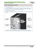
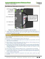
Figure 4-7: Rear View Showing Rear Panel Nut & Latch Locations
9. Loosen (but
DO NOT
REMOVE
) the top nut and slide a thin metal object (such as a
hacksaw blade) between the rear plate and the fiber material of the rear refractory to
separate the material from the plate.
CAUTION!
The rear plate weighs approximately 40 pounds. It is therefore recommended that 2 people
remove the plate.
10. Remove the top nut from the plate and remove it from the unit.
11. Optionally, you can thread 2 small nipples into the rear plate to act as handles, which will
ease removal and reinstallation.
12. Refer to Figure 4-8 and note the position of the rear refractory. Prior to refractory removal,
mark as necessary using a permanent marker or tape.
13. Gently pull on the two opposing metal tabs located on the outer edge of the fiber blanket,
then alternately pull on the other two opposing tabs. Continue this process until the fiber
refractory package can be removed from the combustion chamber. Be careful not to drop
or damage the refractory.
14. Place the fiber insulation package, metal face down, in a safe location to avoid damage.
15. The combustion chamber can now be viewed and inspected with a full view of the Burner
assembly and rear tubesheet. A borescope can be used to inspect the front tubesheet as
well as under the expansion joints.
16. Following inspection, reinstall the components in the reverse order in which they were
removed.
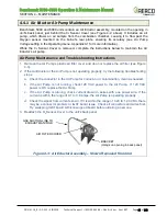
LEFT REAR PANEL
SPRING LATCH
RIGHT REAR PANEL
SPRING LATCH
Access the rear panel nuts
(behind arrows) are on the
rail & base inside the unit,
accessible after removing
the side panel on each
side.
O
2
SENSOR COVER
LOCATION
(cover removed)
AIR EDUCTOR

