Benchmark 5000-6000 Operation & Maintenance Manual
SECTION 4
– MAINTENANCE
OMM-0118_B
•
GF-203
•
5/9/2019
Technical Support
•
(800) 526-0288
•
Mon-Fri, 8 am - 5 pm EST Page 53 of 148
Rear Refractory Replacement Instructions
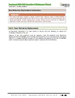
IMPORTANT!
If the rear refractory (P/N 83027) was damaged during removal, it should be replaced with a
new part. If rear refractory replacement is required, a 2 hour burn-in period at a 30% fire
rate must be performed to drive off organic binders. These organic binders are not
hazardous materials, however they may emit an odor similar to burning wood.
17. Tighten the bolts on the rear plate using an alternating pattern to ensure a uniform seal.
Torque bolts to approximately
20 ft-lbs
.
18. To avoid exhaust leaks, ensure that a uniform seal is established when reconnecting the
flue system to the boiler.
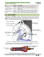
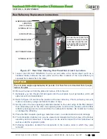
Figure 4-8: Partial Rear View Showing Rear Burner Plate
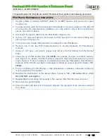
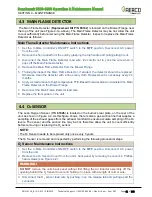
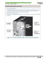
Figure 4-9: Partial Rear View
–
Rear Plate and Refractory Removed
METAL TABS
(4 EACH)
REFRACTORY
REFLECTOR
THERMAL SWITCH
REAR BURNER PLATE
O
2
SENSOR
GAS SUCTION LINE
FROM EXHAUST
MANIFOLD
AIR EDUCTOR
ASSEMBLY

