5
KIT CONTENTS
We have organized the parts as they come out of the box for easier identification during assembly. Before you begin
assembly, group the parts like we list them. This will ensure that you have all of the parts before you begin assembly and
it will also help you become familiar with each part.
AIRFRAME ASSEMBLIES
❑
{1} Molded Plastic Fuselage
❑
{1} Right Wing Panel
❑
{1} Left Wing Panel
❑
{1} Horizontal Stabilizer w/Elevator
❑
{1} Vertical Stabilizer w/Rudder
❑
{1} Molded Clear Canopy
MOTOR ASSEMBLY
❑
{1} Speed 380 Motor
❑
{1} 5 x 2.5 Nylon Propeller
❑
{1} Propeller Adapter Set
❑
{1} Aluminum Motor Plate
❑
{1} Spinner Assembly
❑
{2} 2.5mm x 4mm Machine Screws
❑
{1} Velcro Strip
CONTROL ASSEMBLIES
❑
{2} Threaded Pushrod Wires
❑
{2} Nylon Control Horns w/Backplates
❑
{2} Nylon Clevises
❑
{1} Foam Servo Tray
❑
{1} Servo Tray Reinforcement Board
MISCELLANEOUS ITEMS
❑
{1} 4mm x 60mm Aluminum Tube
❑
{1} 4mm x 70mm Aluminum Tube
❑
{4} 4mm Nylon Sleeves
❑
{1} Wing Center Section Reinforcement Board
❑
{1} Wing Trailing Edge Reinforcement Board
❑
{1} Stabilizer Reinforcement Board
❑
{4} Rubber Bands
❑
{1} Decal Sheet
❑
{2} 2mm x 5mm Wood Screws
❑
{12}1mm x 4mm Wood Screws
☛
Before beginning assembly, we recommend that you
first break in the motor. Taking the time to do this now
will do a couple of things. First, it will improve the per-
formance and life of the motor and, second, it will give
you a chance to test your radio system, ESC and flight
battery before installing them into the airplane.
❑
1)
Lay the motor, flight battery, charger, radio sys-
tem and electronic speed control onto your work table.
❑
2)
Charge the flight battery using your peak charger,
following the instructions that were provided with the
charger. Install 8 AA batteries into the Focus 3 transmitter.
❑
3)
Plug the two servo leads and the ESC lead into
their proper slots in the receiver. Carefully solder the ESC
motor leads to the back of the motor. The mounting tab
with the red dot next to it is the positive tab.
MOTOR BREAK-IN
TOOLS AND SUPPLIES REQUIRED
❑
Needle Nose Pliers
❑
Trinity Break-In Drops
❑
Performance Plus Motor Spray
❑
Paper Towels
BREAKING IN THE MOTOR
☛
You will still be able to install the motor into the air-
plane even with the ESC soldered in place. If you are
using the Wattage IC-14 ESC, soldering is not required.
❑
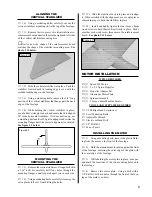
4)
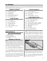
Set the motor between the handles of a pair of
needle nose pliers and secure the motor to the handles
using a couple of small rubber bands. This will keep the
motor secure enough for the break-in procedure. See
photo # 1 below.
Photo # 1
☛
Don't use the rubber bands included with the kit. They
are used to hold the wing in place and you don't want
them to be damaged by any solvents used for break-in.
❑
5)
Turn on the transmitter and plug the flight bat-
tery into the speed control. Make sure the throttle is at
idle and the motor is turned off.


