Watt Drive L2000 Series Manual Download Page 17

Appearance and names of parts

Page 17 / 52

Notes on technical specifications:

Note 1

: Protective structure is based upon EN60529

Note 2

: The applicable motor is a WATT DRIVE standard four-pole motor. When using

another motor, make sure that the rated motor current does not exceed the rated inverter
current.

Note 3

: The output voltage will decrease if input voltage decreases.

Note 4a

: The initial data setting values of 005N/011N are same as 007N/015N. So be sure

to set the correct values under 

b 12

 and 

b 22

 of 005N/007N for each motor first.

Note 4b

: The initial data setting value of 030H is same as 040H. So be sure to set the

values under 

b 12

 and 

b 22

 of 030H for the motor first.

Note 5

: Confirm with the motor manufacturer the motors maximum rpm when using a motor

running at frequencies higher than 50/60Hz

Note 6

: Torque will be reduced when the base frequency exceeds 50Hz.

Note 7

: In the range of 40 to 50°C reduce the carrier frequency to 2kHz and derate the

output current to 80% of the rated current, and remove the top cover.
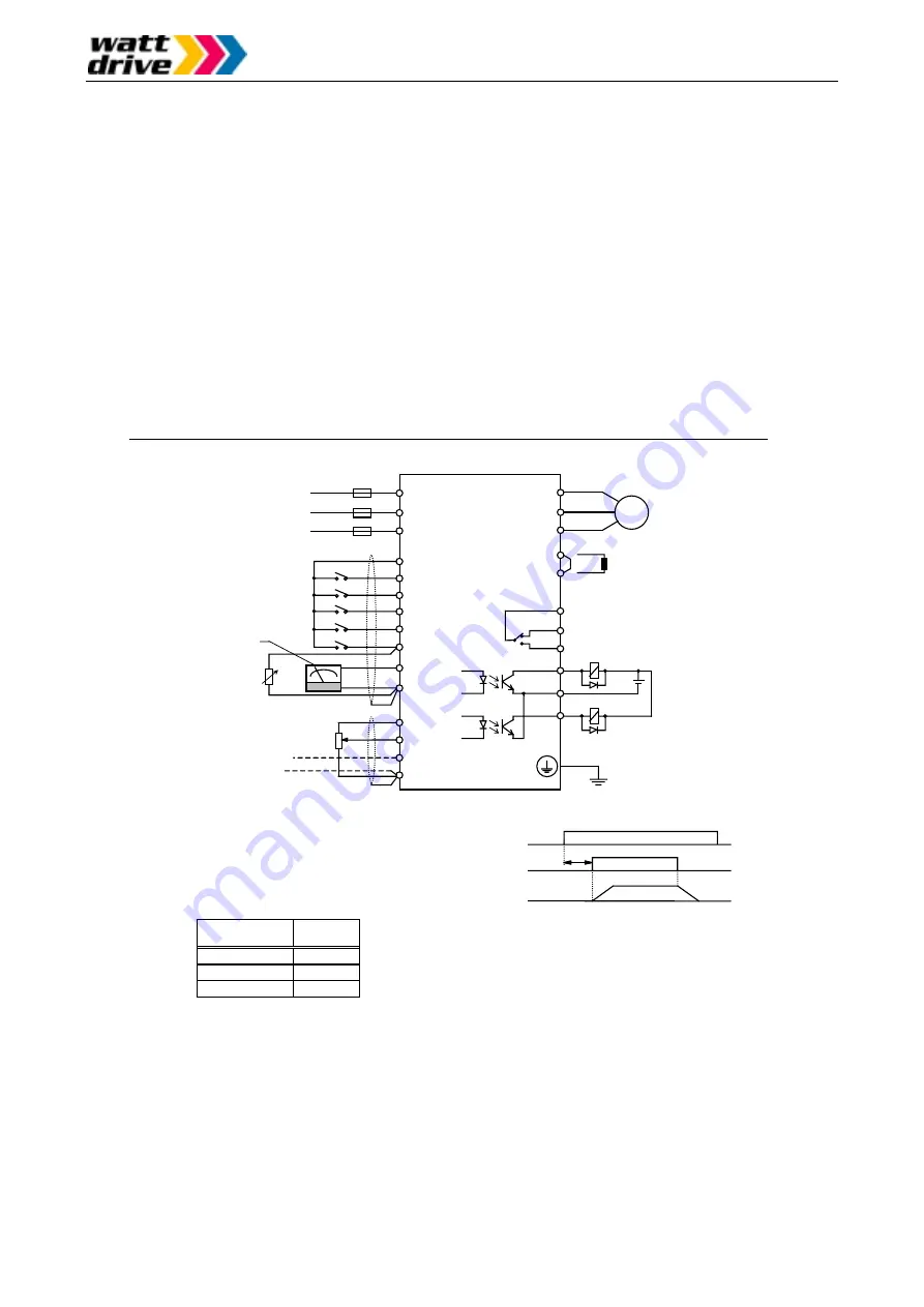
Power supply

(three phase)

50/60 Hz

Fuses

L2000 series

inverter

L1 (L1)

L2

L3 (N)

T1 (U)

T2 (V)

T3 (W)

1
2
3
4

5

L

P24

H
O

OI

L

FM

AL0

AL1
AL2

11

CM2

12

Motor

+1

+

Ground

Alarm signal

(relay output)

°

C

Thermistor

Frequency

monitor

Set value input

4 – 20 mA

Analog set value 0 – 10V

(Pot 1k – 2k Ohm)

Power supply

Running command

Output frequency

> 2 s

The common potential depends

on the terminals used:

Terminals

Common

potential

1, 2, 3, 4, 5

P24

FM, H, O, OI

L

11, 12

CM2

Notes:

24VDC

Short bar must be removed

if the inductor is connected

A trip will occur when a running command is active at the time the

power supply is switched on. The power supply should not be

switched on simultaneously with the running command; instead

there should be a time delay of about 2 seconds from the time the

power supply is switched on until the running command is activated

(refer to time diagram). Also the power supply must not be switched

off while the running command is being active (motor is running).

Summary of Contents for L2000 Series

Page 1: ...INVERTER Series L2000 M A N U A L NB596XA...

Page 2: ...ovides you with the information necessary to install start up and operate the L2000 frequency converters It is recommended that this manual is read thoroughly before powering up the frequency converte...

Page 3: ...online de WATT DRIVE Nord GmbH D 51429 Bergisch Gladbach Vertriebs und Servicecenter K ln Tel 49 2204 84 2800 Fax 49 2204 84 2819 e mail watt koeln t online de WATT DRIVE D 97044 W rzburg Vertriebs u...

Page 4: ...vicing drives and electronic controllers there might exist exposed components with cases or protrusions at or above line potential Extreme care should be taken to protect against shock For these reaso...

Page 5: ...ain terminals or other hazardous terminals for any interconnection terminals for connecting the motor contact breaker filter etc must be inaccessible in end installation All of the above instructions...

Page 6: ...EMC is only ensured if the suitable filter is selected for the particular drive and installed in accordance with these EMC recommendations Please choose the appropriate filter using the table below In...

Page 7: ...d motor housing Very often the terminal boxes and particularly the threads for the metal PG screw connections are painted Make sure there is always a good metallic connection between the shielding of...

Page 8: ...2800 1978 1978 Dimensions single wire litze 4 4 mm 4 4 mm 4 4 mm 4 4 mm 4 4 mm 4 4 mm Output cable 3x1 5mm 3x1 5mm 3x2 5mm 4x1 5mm 4x2 5mm 4x2 5mm Weight in kg approx 0 5 0 6 1 0 0 7 1 1 2 4 Heat dis...

Page 9: ...ONTROL TERMINALS 23 GENERAL REMARKS 24 WIRING EQUIPMENT AND OPTIONS 26 TERMINALS 28 7 GENERAL OPERATION NOTES 31 BEFORE STARTING OPERATION 31 TEST RUN 31 8 CONTROL CIRCUIT TERMINAL FUNCTIONS 33 OVERVI...

Page 10: ...id mist salt damage etc Otherwise there is a danger of fire CAUTION The wall surface on which the inverter is mounted must be of a nonflammable material such as a steel plate Wiring WARNING The invert...

Page 11: ...that the driven motor or machine does not endanger personnel even in the case of a sudden restart Otherwise there is a danger of injury WARNING Even if the power supply is cut off for a short period o...

Page 12: ...signals e g using a multimeter during operation CAUTION Never stop motor operation by switching off the electromagnetic contactors on the primary or secondary side of the inverter Motor Inverter Earth...

Page 13: ...nvolving a general purpose inverter a large peak current flows on the power supply side sometimes destroying the converter module A The unbalance factor of the power supply is 3 or higher B The power...

Page 14: ...on number 1 2 Distribution for E Europa U USA Type of inverter F with digital operator Input voltage N 200V single three phase H 400V three phase L three phase 200V only Motor capacity 002 0 20kW 022...

Page 15: ...requency setting External signals 0 10VDC input impedance 10k Ohm 4 20mA input impedance 250 Ohm Potentiometer 1k 2k Ohm 1W Dig operator Via keys RUN for start and STOP RESET for stop Default setting...

Page 16: ...m Potentiometer 1k 2k Ohm 1W Dig operator Via keys RUN for start and STOP RESET for stop Default setting forward run Forward Reverse run Start Stop Ext signals Intelligent input terminals configurable...

Page 17: ...e of 40 to 50 C reduce the carrier frequency to 2kHz and derate the output current to 80 of the rated current and remove the top cover Power supply three phase 50 60 Hz Fuses L2000 series inverter L1...

Page 18: ...L2000 series inverters Legend A Control terminals B Alarm terminals C Main terminals D Grounding terminals All dimensions are in millimeters L2000 002 NFE 004 NFE L2000 004 HFE 005 NFE 007 NFE L2000...

Page 19: ...Note 1 Digital operator can be opened Note 2 Serial interface Screw Note 2 Control terminals Grounding terminal PE Grounding terminal PE Control terminals Alarm terminals Rear cover Mains circuit ter...

Page 20: ...r cover Control terminals Mains circuit terminals Alarm terminals Key cover opened Casing Cooling fin Serial interface Digital operator can be opened Anm 2 Key cover Control terminals Mains circuit te...

Page 21: ...he figure are only meant for reference A more compact installation back to back may well be possible and should be discussed with WATT DRIVE Please always leave enough room for the key cover to be ope...

Page 22: ...ent For these reasons the following items should be observed Only pulse current sensitive earth leakage circuit breakers which have a short term delay and a higher trigger current 500mA should be used...

Page 23: ...t terminals as follows Connect single phase power supply 50 60Hz to terminals L1 L3 N Connect three phase power supply 50 60Hz to terminals L1 L2 L3 N 5 Don t remove the short bar between the terminal...

Page 24: ...therwise the surge voltage created when the relay goes on or off may damage the output circuit Be sure that the specified grounding is carried out Separate the inverter s grounding pole from those of...

Page 25: ...supply terminal left half of figure below and when using a separate external 24VDC power supply right half of figure below L2000 series frequency inverter L1 L1 L2 L3 N T1 U T2 V T3 W 1 2 3 4 5 L P24...

Page 26: ...007NFE 1 1 L2000 011NFE 2 5 mm2 AWG 13 16 A 1 5 L2000 015NFE 4 0 mm2 AWG 11 25 A single phase 16 A three phase 2 2 L2000 022NFE 4 0 mm2 AWG 11 40 A single phase 25 A three phase 0 4 L2000 004HFE 1 5...

Page 27: ...rt is used to conform with the applicable EMC standards DC reactor This part is used to improve the power factor Radio noise filter This part reduces noise generated at the output of the inverter this...

Page 28: ...er supply and motor are listed Location of power terminals Inverter model Screw size Width in mm L1 L2 L3 N T1 U T2 V T3 W 1 002NFE 004NFE M3 5 7 1 L1 L2 L3 N T1 U T2 V T3 W 1 007NFE 022NFE 004HFE 040...

Page 29: ...Three phase supply connect to L1 L2 L3 U V W bzw T1 T2 T3 Inverter output Connect a three phase motor 1 External DC reactor Normally a short bar is attached between terminals 1 and When a DC reactor i...

Page 30: ...r monitor signal H Reference for frequency command input 10V DC max 10mA O Voltage frequency command Set value 0 10V Input impedance 10k Ohm OI Current frequency command Set value 4 20mA Input impedan...

Page 31: ...ncy parameter must be chosen in accordance with the maximum frequency of the connected motor and machine 10 Do not operate the inverter with the front case opened Make sure the front case is completel...

Page 32: ...pressing the RUN key the motor starts to run and the RUN lamp lights up 5 The actual frequency can be monitored using function d 01 6 You can stop the test run by pressing the STOP key CAUTION After...

Page 33: ...can be programmed as a PTC thermistor input using C 05 The terminal L serves as common for the thermistor input AT 16 Activate input OI cur rent set value 4 20mA When the AT input is activated then th...

Page 34: ...tal output is configured as FA1 then a signal is output as long as the output frequency is held constant at set value With a digital output being configured as FA2 a signal will be output as long as t...

Page 35: ...in memory UP Key DOWN Key These keys are used to change data and parameters FUNC Key This key is used for setting up data and parameters RUN Key This key is used for starting When terminal run is sele...

Page 36: ...2 A 02 060 0 0 0 F 01 A 50 0 d 01 F 01 Data is stored Turn power on Data is stored Press continuously Data is stored Start run Monitoring actual output frequency Extended function of A Group Frequency...

Page 37: ...up C exten ded functions START key This key starts the L100 inverter The set value of F004 deter mines forward or reverse run STOP key This key stops the L100 inverter When a trip occurs this key beco...

Page 38: ...Y Setting range 0 1s 3000s Resolution 0 1s in the range of 0 1 through 999 9 Resolution 1s in the range of 1000 through 3000 10 0 Deceleration time 1 F 03 Y Setting range 0 1s 3000s Resolution 0 1s in...

Page 39: ...r OI terminal and thus determine the amount of filtering for harmonics that may be present with the analog signal 1 Little filtering fast reaction to changes in set value 8 Extensive filtering slow re...

Page 40: ...nction description parameter setting range Standard setting Set values DC braking L2000 series inverters have a configurable DC brake that is activated as soon as the stop command is issued By applyin...

Page 41: ...en designed with a control variable of frequency in Hz where the proportional gain kp the integral gain TN and the differential gain TV of the control algorithm can be set independently from each othe...

Page 42: ...5 Although these gains can be set independently of each other there are interactions between them When the P gain kp is changed the effective I gain changes TN also Only when kp 1 the effective I gai...

Page 43: ...be reduced under A 45 to the rated motor voltage Example With a mains supply voltage of 440V and a motor rated voltage of 400V the parameter 440 has to be entered under A 82 and 91 400 440 100 has to...

Page 44: ...igured acceleration time 03 After the time set under b 03 has elapsed the inverter synchronizes to the motor s current speed and the motor is decelerated using the configured deceleration time Afterwa...

Page 45: ...the configured overload limit is reached the frequency will be reduced within the time entered here setting range 0 1s Hz 30s Hz Important note Do not enter values below 0 3 1 0 Function Display Funct...

Page 46: ...row keys and the FUNC key simultaneously While holding down the keys mentioned above press the STOP key shortly and wait about 3 seconds for the LED display to show the message d 00 in a blinking mann...

Page 47: ...t stop forward run 01 RV start stop reverse run 02 CF1 1 multistage frequency input 03 CF2 2 multistage frequency input 04 CF3 3 multistage frequency input 05 CF4 4 multistage frequency input 06 JG jo...

Page 48: ...put terminal can be used to output one of the following values 00 Output frequency display analog signal 0 10VDC 01 Motor current display analog signal 0 10VDC 100 of the rated current corresponds to...

Page 49: ...so cause motor heating and low torque The inverter is shut off when the DC bus voltage goes below a certain level E009 CPU error Malfunction or abnormality of the CPU The inverter is shut off E011 E02...

Page 50: ...ings have been selected and the inverter currently is in its initializing phase refer to functions b 84 and b 85 The parameters for the European market EU are loaded For non European inverter models t...

Page 51: ...1 been selected Has the correct source for the running command A 02 been selected Correct the A 01 parameter setting if necessary Correct the A 02 parameter setting if necessary The motor won t start...

Page 52: ...ter the power supply was left in the on state for only less than 6 seconds Copy the parameter settings once more and then keep the power supply turned on for more than 6 seconds The motor won t start...

Reviews: