

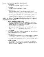


Overview of Key Steps, from Installation through Operation:
1
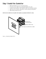
Install the controller
•
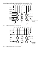
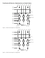
Use the panel knock-out pattern guidelines in this guide.
2
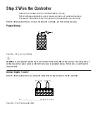
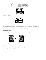
Wire the controller
•
Use the connector/wiring information in this guide.
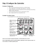
3
Configure the controller
•
After applying power, use the Configuration Mode to enter the equipment
Application Number (from the M
INI
C
HEF
2000 Software Selection table), set up the
controller and access the thermal optimization functions.
•
Set the Application Number Security Lock, if necessary, to prohibit end users from
changing Application Number.
•
To speed configuration, you may want to use the Prototyping/Training Overlay
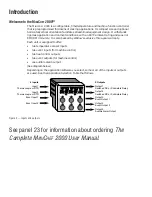
(available separately, see Ordering Information on panel 23).
Note: Always select and enter the application number first. The parameters that follow are based on it. See instruc-
tions in the
Hardware & Software Setup Guide.
4
Program the menus (automatic menu applications only)
•
Use the Program Mode to program automatic menus for the chosen application.
•
To ease menu programming, you may want to use the Prototyping/Training Overlay
(available separately, see Ordering Information on panel 23).
5
Set menu security (automatic menu applications only)
•
Set up menu security, if necessary, to prohibit end users from changing values.
(Because the controller defaults to no security, the end user may be able to access
the Program Mode to change parameter values based on menu.)
6
Set Real-time Clock
This applies only to controllers purchased with the Real-time Clock option. It allows you
to see the time of day instead of “idle” on the display.
7
Design faceplate overlay
•
Use the Overlay Design Guidelines in this guide to design, manufacture and apply a
membrane overlay for the controller faceplate. This custom-designed overlay
becomes the end-user interface.
•
For overlay designs to suit specific applications, see the suggestions in each applica-
tion guide.
8
Operate the M
INI
C
HEF
2000
•
Use the Operation Mode to run the installed controller. This is the default mode.
Operation instructions are included in each application guide (available separately,
see ordering information on back page).
Summary of Contents for MINICHEF 2000
Page 17: ...17 NOTES...
Page 21: ...21 NOTES...


