

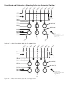

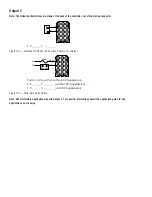
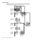


Output 1
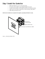
Note: The following illustrations are views of the back of the controller, not of the mating connector.
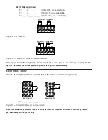
F 2 _ _ – _ 1 _ _ – _ _ _ _
Figure 11a — Switched DC Option (5V nominal, 30mA, non-isolated).
Form A, 0.4A, with or without RC Suppression
F 2 _ _ – _ 2 _ _ – _ _ _ _ (without RC Suppression)
F 2 _ _ – _ 3 _ _ – _ _ _ _ (with RC Suppression)
Figure 11b — Solid-state Relay Option.
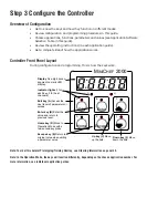
Note: Not all software applications require Output 1. For specific information consult the application guide for the
application you are using.
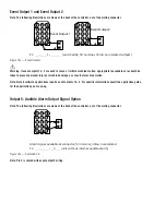
1
2
3
4
1
4
5
6
7
8
9
10
11
12
13
14
15
Ext. Load
Fuse
Com
NO
L1
L2
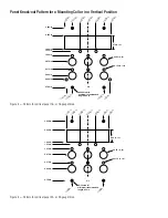
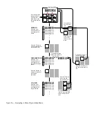
1
2
3
4
1
4
5
6
7
8
9
10
11
12
13
14
15
Ext. Load
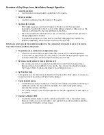
Summary of Contents for MINICHEF 2000
Page 17: ...17 NOTES...
Page 21: ...21 NOTES...