


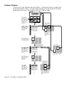
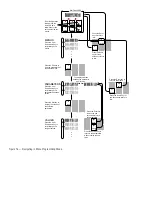


Figure 16 — Navigating in Menu Programming Mode.
[stPt2]
[tinE2]
[FAn`2]
[``32Ï]
[M``1]
[M``2]
[M``3]
•
•
•
•
•
•
B
D
Enter
Home
B
E
Enter
Escape
[``32Ï]
[``33Ï]
[``34Ï]
A
B
D
E
G
H
Enter
Escape
Home
Edit
D
Home
A
Edit
C
F
M
INI
C
HEF
2000
[`idle]
From the Operation
Mode, press the
Up- and Down-
arrow keys for two
seconds to view the
menus.
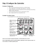
MENUS
Press the Up- or
Down-arrow key to
scroll through the
menus.
PARAMETERS
Press the Up- or
Down-arrow key to
scroll through the
parameters and their
values.
VALUES
Press the Up- or
Down-arrow key to
scroll through the
range of values.
Press the Enter key
to save the new
value and return to
the parameters.
Press the Enter key to
return to the menus.
The display switches
between the parameter
and its value.
Press the Edit key to
view the parameters of
the selected menu.
A
Edit
Press the Edit key to
display the values of
the selected
parameter.
Press the Escape key to
return to the parameters
without saving the new
value.
Press the Home key for
two seconds to return to
idle.
Press the Home
key for three
seconds to return
to idle.
B
Enter
Press the Enter
key to return to
idle.
Summary of Contents for MINICHEF 2000
Page 17: ...17 NOTES...
Page 21: ...21 NOTES...


