9
STEP 5
ATTACH SUPPORT TUBE TO CABINET
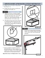
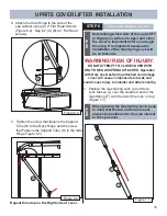
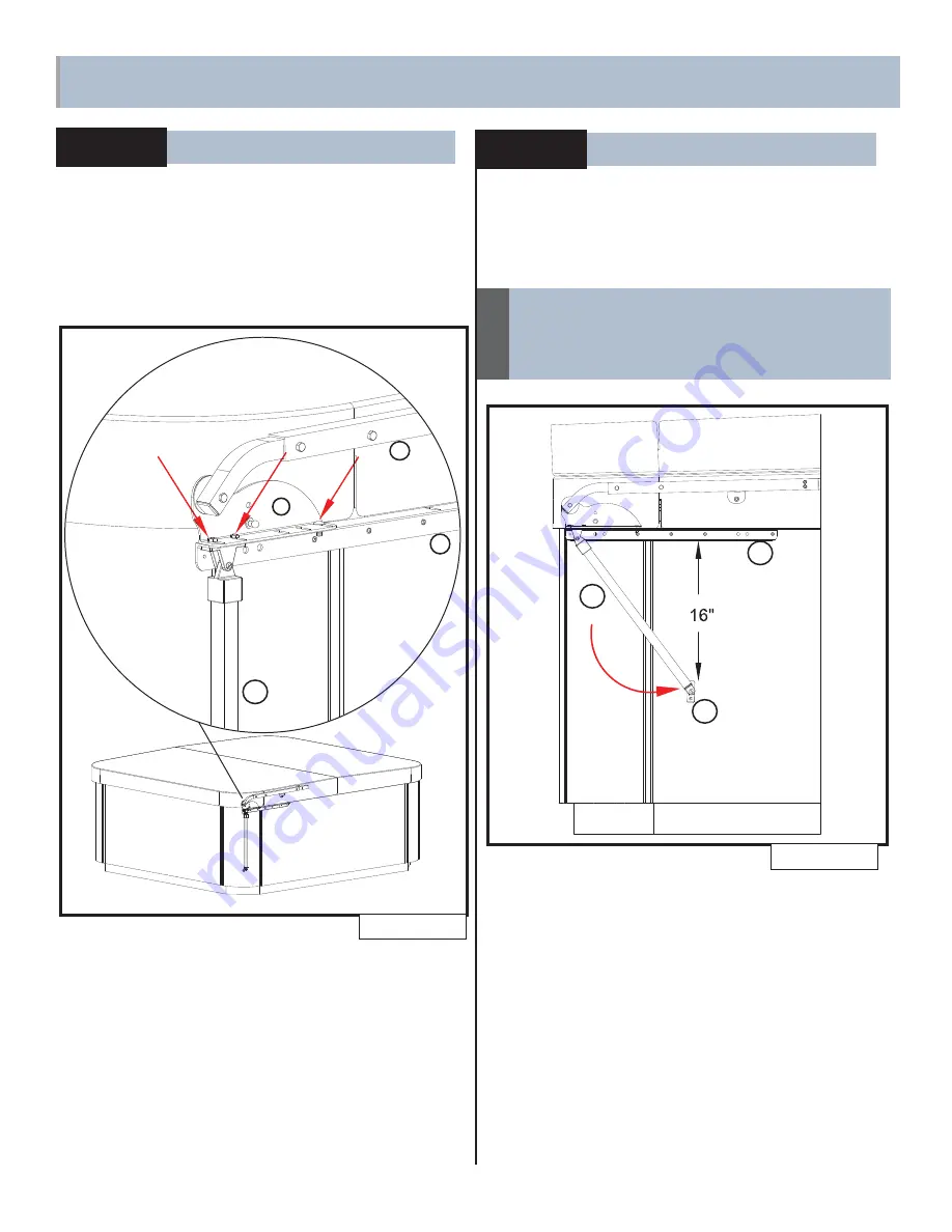
1. Swing the Support Tube (H) forward until
the distance from the bottom of the Auxiliary
Bracket (D) to the top of the Side Hinge (B) is
approximately (16”) (Figure 6.1).
Figure 6.1
H
B
D
The 16” Location may place the Side
Pivot Bracket (B) on a wood seam. Move
the Support Tube (H) slightly in either
direction if this condition exists.
NOTE
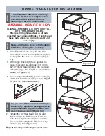
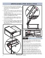
2. Using the Side Hinge (B) as a template, mark
the two holes on the side of the spa cabinet
(Figure 6.2).
3. Drill the two marked holes using a 1/8”
(3mm) bit with approximately 1/2” (12.5 mm)
maximum depth (Figure 6.2).
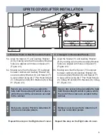
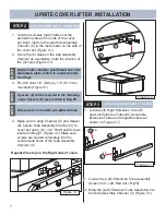
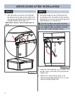
5. After both sides of cover (Left and Right)
are spaced evenly side to side, tighten the
(3) screws that hold the Base Bracket (A) to
Auxiliary Bracket (D) (Figure 5.1).
STEP 4
BASE BRACKET AND AUXILIARY BRACKET
Figure 5.1
D
A
C
H
UPRITE COVER LIFTER INSTALLATION
1
Repeat this step on Left and right side of
cover.
Summary of Contents for UPRITE
Page 15: ...14 NOTES ...
Page 16: ...62732 D 01 20 ...

