background image

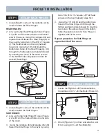
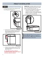
STEP 7

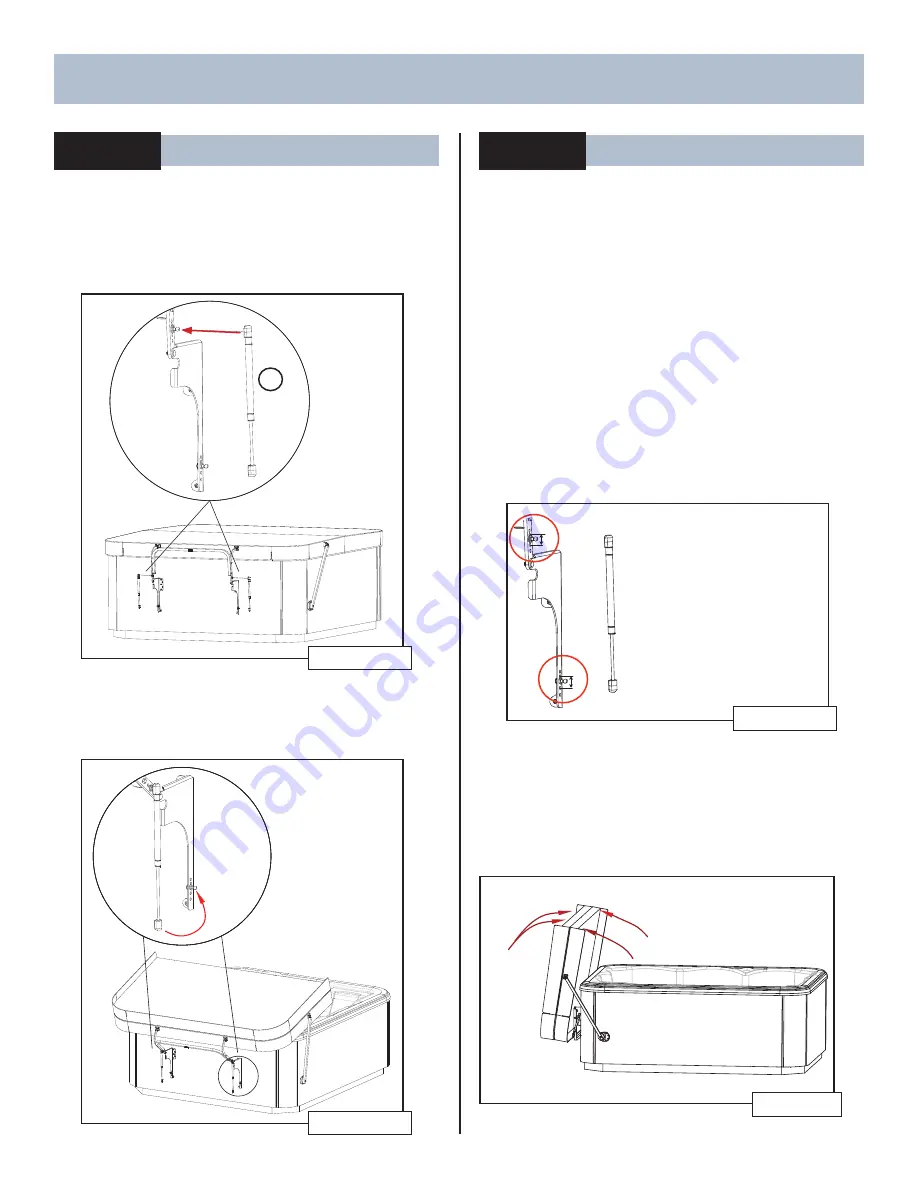
INSTALL GAS SPRING

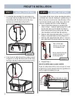
1.  Locate the Gas Springs (C) and snap onto 

the upper ball stud (attached to the Pivot Arm 
Assembly) with the barrel end of the Gas 
Spring up on both sides (Figure 8.1). 

Figure 8.1 

C

2.  Fold Cover in half and pull to position shown 

(Figure 8.2). Snap the lower joint of the Gas 
Springs onto the lower ball stud (Figure 8.2). 

Figure 8.2 

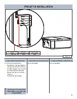
STEP 8

ADJUST GAS SPRING

The motion of the cover when opening should be 
controlled and smooth rotating to a gentle stop. If 
this is how your cover works, skip this step. If the 
cover does not fully open or the cover does not 
come to a gentle rest then do the following:
a.  Remove both Gas Springs by reversing the 

order in Step 7. Remove Gas Springs from each 
ball stud by placing a fl at blade screwdriver 
behind the retaining cup (hold up the clip with 
the screwdriver) and pull Gas Spring away.

b.  Remove both lower ball studs with a ½” wrench.  

Raise or lower ball studs one hole (Figure 9.1) 

c.  Remove both upper ball studs with a ½” wrench. 

Move ball studs in the same direction as in step b.

Move both ball 
studs up one hole 
to increase force

Move both ball studs 
down one hole to 
decrease force

Figure 9.1 

d.  Repeat Step 7

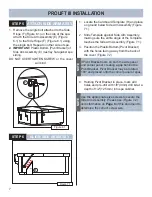
HOW TO OPEN AND CLOSE COVER


Push on either side of the cover to open or close 
(Figure 9.2). Cover should come to a gentle rest 
with a slight tilt towards the spa.

Figure 9.2

Push this side to open

Push 
this 
side to 
close

PROLIFT III INSTALLATION

9

Summary of Contents for ProLift III

Page 1: ...E PLATES PROLIFT III INSTALLATION 4 ATTACH BACK HINGES ATTACH SIDE HINGES ASSEMBLE CROSSLINK PROLIFT III INSTALLATION 5 ATTACH CROSSLINK ASSY PROLIFT III INSTALLATION 7 ATTACH SIDE ARM ASSY ALIGN SIDE...

Page 2: ...lat Head Bag 1 C 2 Gas Spring K 12 10 X 2 Square Pan Head Bag 3 D 1 Crosslink Assembly L 8 10 X 2 Square Flat Head Bag 3 E 2 Side Arm Assembly M 4 20 x Hex Bolt Bag 1 F 2 Side Hinge with Screw Bag 1 G...

Page 3: ...e a minimum of 30 clearance between the wall and the retracting side of the spa for cover to operate properly and 4 on each side for Side Arm clearance The Warning Label on the cover is always the fro...

Page 4: ...er Position the cover evenly on all spa sides See Figure 1 3 Figure 1 4 Warning Label Hidden Aluminum Plate Back Side to Side Wa rni ng La be l The cover warning label must be facing the front of the...

Page 5: ...es SIDE HINGES 2 Line up the top Side Hinge F holes Figure 2 2 with 2 of the marked holes on one side of the cover 3 Using the cordless drill and square drive bit fasten the Side Hinge to the cover by...

Page 6: ...re it is still aligned evenly with the outside edges of the spa bar top Figure 1 3 4 Using the Mounting Bracket bottom part of the Pivot Assembly as a template predrill 1 8 holes into the back of the...

Page 7: ...removable Panels SPAS WITH PLASTIC OR METAL FRAME N A See Page 2 for important information on screw size compatibility NOTE 1 Secure the Mounting Brackets to the spa cabinet using 12 of the Pan Head...

Page 8: ...st Side Arm Assembly making sure the entire angle of the Template touches the Side Arm Assembly Figure 7 1 3 Position the Plastic Bottom Pivot Bracket with the holes facing away from the back of the c...

Page 9: ...le panel spas a Spas with Removable Panels c Spas with Plastic or Metal Frame SPAS WITH REMOVABLE PANELS SPAS WITH NON REMOVABLE PANELS N A L 4X See Page 2 for important information on screw size comp...

Page 10: ...the following a Remove both Gas Springs by reversing the order in Step 7 Remove Gas Springs from each ball stud by placing a flat blade screwdriver behind the retaining cup hold up the clip with the...

Page 11: ...10 PROLIFT III INSTALLATION Always ease the cover to the Open and Close Position to avoid Slamming thereby prolonging the service life of your cover NOTE BLANK...

Page 12: ...RT QUANTITY DESCRIPTION P 1 Top Mounting Bracket Spacer Left R 1 Top Mounting Bracket Spacer Right S 1 Bottom Mounting Bracket Spacer Left T 1 Bottom Mounting Bracket Spacer Rigth W 1 Side Pivot Brack...

Page 13: ...Figure 1 1 Figure 2 1 IMPORTANT Make sure holes are facing towards the middle of the spa STEP 1 ALIGN MOUNTING BRACKET WITH SPA 1 Rotate Pivot Assemblies until the bottom Mounting Bracket touches the...

Page 14: ...the back Then position arm so rib of side spacer fits into appropriate groove Predrill 7 64 holes into the spa Figure 5 1 with 1 max depth There are 4 holes per Pivot Bracket Important Make sure that...

Page 15: ...14 Figure 6 2 PROLIFT III SPACERS BLANK...

Page 16: ...62701 E 04 19...

Reviews: