2
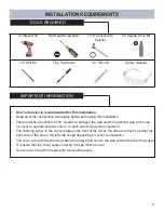
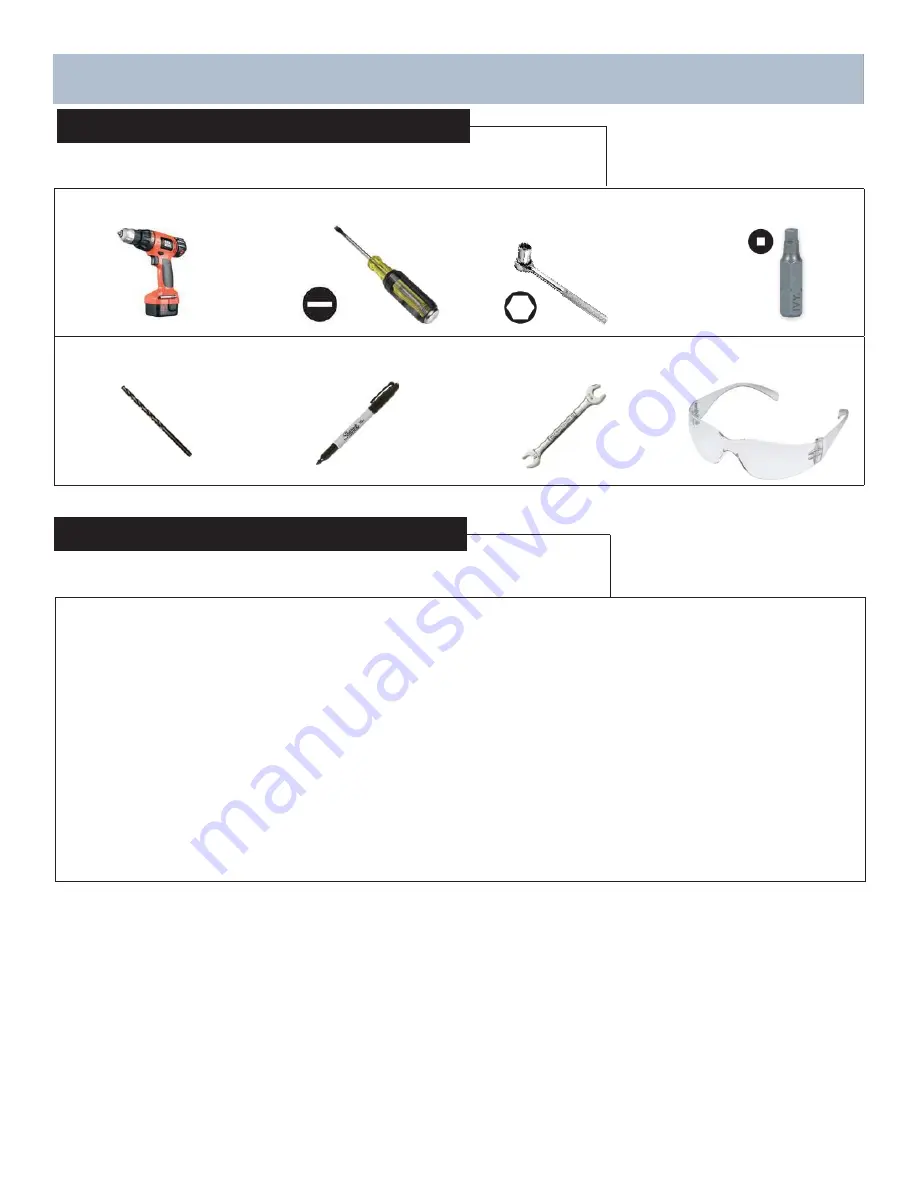
Cordless Drill
Flat Head Screwdriver
7/16” Socket with
Ratchet
#2 Square Drive Bit
1/8” Drill Bit
Fine Tip Marker
1/2” Wrench
Safety Glasses
INSTALLATION REQUIREMENTS
TOOLS REQUIRED
IMPORTANT INFORMATION
• One Technician is recommended for this installation.
• Read all of the instructions thoroughly before performing this installation.
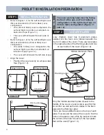
• There must be a minimum of 30” clearance between the wall and the retracting side of the spa
for cover to operate properly and 4” on each side for Side Arm clearance.
• The Warning Label on the cover is always the front of the cover; the lifter will attach on either the
back side of the spa or the left side of spa depending on cover confi guration.
• The cover side with the Warning Label will always fold over to the side without the Warning Label.
• To ensure that the cover seals correctly, the spa must be level.
• Use screws in bag #3 on spas with removable panels.
Summary of Contents for ProLift III
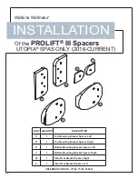
Page 15: ...14 Figure 6 2 PROLIFT III SPACERS BLANK...
Page 16: ...62701 E 04 19...

