


F-1031, Section 4307
Page 2 of 12
Disassembly of the Transmission
The transmission consists of three sections; the cap, the mid-section and the
bottom section. The order of disassembly is bottom section, mid-section and
cap.
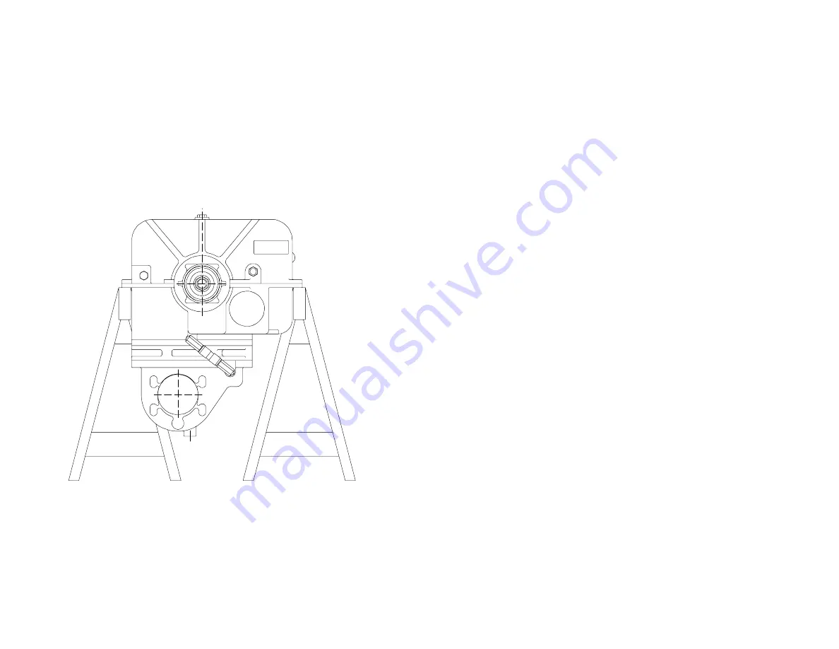
NOTE: Out of chassis overhaul will require supporting the transmission
initially in an upside down position, possibly attaching it directly to an
engine overhaul stand at the face of the cap that bolts to the pump or
making up an adapter to allow this connection to an overhaul stand.
Another consideration would be to support on the underside of the
flange of the mid-section, first removing the flange bolts at the support
areas (see Figure 1).
Figure 1. Transmission Supports
IL2153
1.
Remove companion flanges or end yokes from drive and coupling shafts.
2.
Remove lube systems hoses by disconnecting hoses (T67) and (T64) at
swivel fittings (T66), tee (T102) and elbow (T57). Remove sump oil
strainer (T132) from bottom section of case (T28).
3.
Remove cap screws (T8 prior to 5/06/04 or T241 after 5/06/04) and lock
washers (T9) attaching drive shaft housing to bottom section. Loosen cap
screws (T8 and T241) attaching housing to mid-section.
4.
Remove cap screws (T8 on 2” or 2.35” before 5/06/04 - T241 after
5/06/04) attaching the coupling shaft housing (T42) to mid-section and
case bottom.
5.
Remove coupling shaft housing (T42), shims (T41) and O-ring (T182 after
4/25/93).
NOTE: Remove coupling shaft, components and housing as a unit
from case by pulling on the shaft while tapping side to side on the
housing.
6.
Remove cap screws (T52), bolts (T93) nuts (T69) and lock washers (T53)
attaching bottom section to mid-section. Drive dowels (T131) from bottom
section. Separate bottom section and mid-section.
7.
Rotate drive sprocket (T5) and chain (T18) until removable connection pin
set (T83) of the chain is visible. The pin set has a spring pin (T108) in
each end holding it in place (see Figure 8).
8.
Remove spring pin (T108) from drive shaft housing side of long connecting
pin, tap both connecting pins from the chain. Disengage chain (T18) from
the drive (T5) and driven (T26) sprockets and remove from case.
Mechanical Tachometer
9.
Remove tachometer driven gear sleeve (T90) and driven gear (T89) from
drive shaft housing (T11).
Electronic Tachometer
10. Remove magnetic pick-up (T180) from drive shaft housing (T11).
11. Remove the remaining cap screws attaching the drive shaft housing (T11)
to the mid-section. The housing (T11), drive shaft (T13), drive sprocket
(T35), shift collar (T4), shift fork (T80) and associated parts can be lifted
out of the mid-section. The shift fork (T80) will slip off the shaft (T46) as
the parts are lifted up as an assembly. Remove shifter shoe (T40) from
locking arm (T38).
12. Remove locking arm (T38) from pivot pin (T37). Note that the pivot pin
(T37) and shift shaft bushings (T112) need only be removed if bent or
otherwise damaged.
13.
Electric Shift Cases:
Remove pin (T54 - prior to 12/20/02) or shoul‐
der bolt (T237) and self-locking nut (T238 - after 12/20/02) from sector
gear (T47). Remove sector gear from shift shaft. The removal of the pin
(T54) or shoulder bolt (T237) will release the tension on the shift arm
spring (T61). Remove shift shaft spring (T61). Remove sector gear (T47)
from shift shaft.
Summary of Contents for Y Series
Page 14: ......


