4
TRUCLIMATE 500 INSTALLATION GUIDE
General Installation Information: Refrigerant Detection and Mitigation
Example: For instance, if your elevation is 5249Ft (1500mm)
your area factor would be 1.12. If your charge weight is 80oz
(2.268 kg) at a floor height installation. The Amin would be
516 square Ft (48.0 square meters). Take 516 square ft x 1.12
for a new Amin of 577.92 square feet (53.76 square meters).
H
alt
AF
meter
ft
0
0
1.00
200
656
1.00
400
1312
1.00
600
1969
1.00
800
2625
1.02
1000
3281
1.05
1200
3937
1.07
1400
4593
1.10
1600
5249
1.12
1800
5906
1.15
2000
6562
1.18
2200
Not recommended
2400
2600
2800
3000
3200
In cases where the minimum room area cannot be met, venti-
lation must be provided from either the equipment enclosure,
natural ventilation to the adjacent space, or provide mechani-
cal ventilation in the room.
2. Machine Room
Equipment containing R-454B refrigerant may be installed,
operated, and stored in a machinery room and shall comply
with applicable sections of ANSI/ASHRAE 15 (USA) or CSA
B52 (Canada). To intergrate the mitigation control at the room
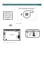
level into the unit leak detection control, see Figure C for
require field wiring instructions.
3. Ventilated Room
Equipment containing R-454B refrigerant shall be installed,
operated, and stored in a room with floor area larger than the
area defined in the “Minimum Floor Area” chart based on the
total refrigerant charge in the system per UL60335-2-40. This
requirement applies to indoor equipment with or without a
factory refrigerant leakage sensor. If a permanent vent is used
to exhaust air from A1 to EAmin, Qmin, the minimum volumet-
ric fl ow of air is provided in Table 1.
Refrigerant Leak Detection and Mitigation
Each chiller unit is provided with A2L leak detection sensors
and alarm output from the Aurora Control. This allows the leak
detection strategy to occur at the chiller unit level and the
leak mitigation strategy to occur at either the room level or
the chiller unit/bank level depending on the application.
Room Ventilation Method
.*"'$!#
##
! $!#(
/*"'$!#
"#
(
0*"'$!#
##
! $!#(
###!$!
!%"
!!#*
#"&#
3-002+/+1-)$!#!
#*
#$"#'
&#.2
! $!#"*
#"&#
3-002+/+1-)$!#!
#*
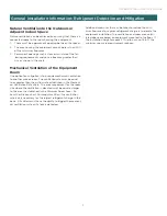
1. Unventilated Room
Determine the total refrigerant charge in the system. In pack-
aged systems, the factory charge should be the total charge
for the system and there should not be a reason for adding
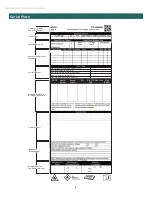
charge in the field. The equipment serial plate and unit Physi-
cal Data table should serve as reference for the total charge.
Use Table 1 to determine the minimum floor area, Amin.
The equipment must be installed with a minimum floor area
equal or larger than the area listed in the chart based on the
total refrigerant charge of that system. If the area is not large
enough, you must move to next step for additional installation
requirements.
When the location of the installation is above 1969 ft (600m),
the Altitude Adjustment Factor in the table is needed to cal-
culate the minimum room size”.
Check that cabling will not be subject to wear, corrosion, excessive
pressure, vibration, sharp edges or any other adverse environmental
effects. The check shall also take into account the effects of aging or
continual vibration from sources such as compressors or fans.
WARNING
.
/
0
!#
#
Permanent
Vent
MODULAR CHILLER BANK
FLOOR AREA, A
1
EA
min


