background image

14

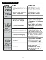
16 . E3, Err – 1003, 

Err – 103 = Control 

valve motor ran 

too long and was 

unable to find the 

next cycle position .

 A.  Drive bracket not snapped in properly and out 

enough that reduction gears and drive gear do not 

interface.

 A.  Snap drive bracket in properly then Press 

NEXT and REGEN buttons for 3 seconds to 

resynchronize software with piston position 

or disconnect power supply from PC board 

for 5 seconds and then reconnect.


17 .   E4, Err – 1004, 

Err – 104 = Control 

valve motor ran too 

long and timed out 

trying to reach home 

position .

 A.  Drive bracket not snapped in properly and out enough 

that reduction gears and drive gear do 

not interface.

 A.  Snap drive bracket in properly then Press 

NEXT and REGEN buttons for 3 seconds to 

resynchronize software with piston position 

or disconnect power supply from PC board 

for 5 seconds and then reconnect.

 B.  Piston not connected to drive cap.

 B. Connect or replace (if damaged) piston/drive cap.


18 .     Err – 1006, Err – 106, 

Err – 116 = MAV/ 

SEPS/ NHBP/ AUX 

MAV valve motor 

ran too long and 

unable to find 

the proper park 

position .


Motorized Alternating Valve = MAV


Separate Source = SEPS


No Hard Water Bypass = NHBP


Auxiliary MAV = AUX MAV

 A.  Control valve programmed for ALT A or B, 

nHbP, SEPS, or AUX MAV with out having 

a MAV or NHBP valve attached to operate 

that function.

 A.  Press NEXT and REGEN buttons for 3 seconds 

to resynchronize software with piston position 

or disconnect power supply from PC board for 

5 seconds and then reconnect. Then reprogram valve 

to proper setting.

 B.  MAV/NHBP motor wire not connected to 

PC board.

 B.  Connect MAV/NHBP motor to PC board two pin 

connection labeled DRIVE. Press NEXT and REGEN 

buttons for 3 seconds to resynchronize software 

with piston position or disconnect power supply 

from PC board for 5 seconds 

and then reconnect.

 C.  MAV/NHBP motor not fully engaged with reduction 

gears.

 C.  Properly insert motor into casing, do not force into 

casing Press NEXT and REGEN buttons for 

3 seconds to resynchronize software with piston 

position or disconnect power supply from PC board 

for 5 seconds and then reconnect.

 D.  Foreign matter built up on piston and stack 

assemblies creating friction and drag enough 

to time out motor.

 D.  Replace piston and stack assemblies. Press NEXT 

and REGEN buttons for 3 seconds to resynchronize 

software with piston position 

or disconnect power supply from PC board 

for 5 seconds and then reconnect.


19 .    Err – 1007, Err – 

107, Err – 117 = 

MAV/ SEPS/NHBP/

AUX MAV valve 

motor ran too short 

(stalled) while 

looking for proper 

park position .


Motorized Alternating Valve = MAV


Separate Source = SEPS


No Hard Water Bypass = NHBP


Auxiliary MAV = AUX MAV

 A.  Foreign material is lodged in 

MAV/NHBP valve.

 A.  Open up MAV/NHBP valve and check piston and 

seal/ stack assembly for foreign material. Press NEXT 

and REGEN buttons for 3 seconds 

to resynchronize software with piston position 

or disconnect power supply from PC board for 

5 seconds and then reconnect.

 B. Mechanical binding.

 B.  Check piston and seal/stack assembly, check 

reduction gears, drive gear interface, and check 

MAV/NHBP black drive pinion on 

motor for being jammed into motor body. 

Press NEXT and REGEN buttons for 3 seconds to 

resynchronize software with piston position or 

disconnect power supply from PC board for 5 

seconds and then reconnect.

 PROBLEM 

CAUSE 

CORRECTION


TROUBLESHOOTING GUIDE

Summary of Contents for ASP-TW

Page 1: ...Installation Instructions Owner s Manual Impression Plus Series Sanitizer Plus Series Twin Water Softeners For Models IMP TW ASP TW IMPRC 1054TW ASP2 1044TW...

Page 2: ...fully and understand the cautions and notes before installing This manual should be kept for future reference If you have any questions regarding your twin water system contact your local dealer YOUR...

Page 3: ...uence of cycles cycle times salt dose exchange capacity and salt dose refill time GENERAL OPERATING DISPLAYS NAVIGATION During normal operation the default user displays are time of day and gallons pe...

Page 4: ...es point in the direction of flow indicated by the engraved arrows on the control valve Water flows through the control valve for normal operation of a water softener or filter During the regeneration...

Page 5: ...le location 3 The media tanks should be installed on a firm level surface above or below grade 4 It is NOT recommended to install any water treatment unit with less than 10 feet of piping between its...

Page 6: ...see drawing Run drain tube to its discharge point in accordance with plumbing codes Pay special attention to codes for air gaps and anti siphon devices CAUTION Never insert a drain line into a drain...

Page 7: ...he water and must be set by an authorized dealer following an on site water analysis Adjusting the number will only impact the frequency of regeneration and will not alter or affect the hardness of th...

Page 8: ...arily press the button to advance the control to the BRINE position 4 With the bypass now in diagnostic mode Fig 3 on page 4 check to verify that water is being drawn from regenerant tank with no air...

Page 9: ...d of time To initiate a manual regeneration immediately press and hold the REGEN button for three seconds The system will begin to regenerate immediately This command cannot be canceled Once a manual...

Page 10: ...ON With some models the manufacturer does NOT recommend the use of any resin cleaners nor placing any resin cleaners into the brine tank Furthermore do not use any salt that indicates it is an iron cl...

Page 11: ...B Connect meter to three pin connection labeled METER on PC board C Restricted stalled meter turbine C Remove meter and check for rotation or foreign material D Meter wire not installed securely into...

Page 12: ...mming Check refill flow control for restrictions or debris and if necessary replace H Damaged seal stack assembly piston H Replace seal stack assembly and or piston I Control valve body type and pisto...

Page 13: ...n the PC board labeled MOTOR Press NEXT and REGEN buttons for 3 seconds to resynchronize software with piston position or disconnect power supply from PC board for 5 seconds and then reconnect B PC bo...

Page 14: ...V NHBP motor to PC board two pin connection labeled DRIVE Press NEXT and REGEN buttons for 3 seconds to resynchronize software with piston position or disconnect power supply from PC board for 5 secon...

Page 15: ...ory screens These do not flash when error occurs A Occurs when dP input is active for ALARM and the input is closed The alarm buzzer will activate and the screen will display the error A Check for low...

Page 16: ...16 This page intentionally left blank...

Page 17: ...17 This page intentionally left blank...

Page 18: ...y cover assembly 1 2 CV3107 01 Motor Assembly 1 3 CV32002 A Drive assembly includes 5 and 6 4 CV3554WS 03 PC board for Sanitizer Plus 1 CV3813WP 03 PC board for Impression Plus 1 5 CV3110 Drive gear 1...

Page 19: ...bly 1 3 CV3135 O ring 228 drive cap o ring 1 4 CV3011 1 piston assembly downflow 1 CV3011 01 1 piston assembly upflow 1 5 CV3174 Regenerant piston 1 6 CV3541 Drive backplate 1 REPLACEMENT PARTS IN OUT...

Page 20: ...20 REPLACEMENT PARTS...

Page 21: ...11 01 T1 transfer drive gear assembly 1 16 CV4012 T1 transfer drive gear axle 1 17 CV4013 T1 transfer reduction gear 1 18 CV3264 WS2H bypass reduction gear axle 3 19 CV3110 WS1 drive reducing gear 12...

Page 22: ...5 CV3395 Chlorine Generator Black 1 CV3395 G SaltMonitor Gray 1 BYPASS VALVE Item No Part No Description Qty 1 CV3006 Bypass assembly 1 2 CV3147 Bypass handles 2 Loosens Injector And Bypass Caps Loose...

Page 23: ...assembly CV3010 1F F injector assembly CV3010 1G G injector assembly CV3010 1H H injector assembly CV3010 1I I injector assembly CV3010 1J J injector assembly CV3010 1K K injector assembly not shown C...

Page 24: ...n 1 Strt No Sil 1 REPLACEMENT PARTS Water flow Proper DLFC orientation directs water flow towards the washer face with rounded edge DRAIN LINE ASSEMBLY 3 4 Item No Part No Description Qty 1 CH4615 Elb...

Page 25: ...4 CH1030 29S 4 x 29 slotted brine well 18 x 33 BT 1 CH1030 36S 4 x 36 slotted brine well 18 x 40 24 x 40 BT s 1 5 CH1018 2 piece overflow set 1 6 CH4500 48 474 air check assembly 1 2 x 48 1 7 CH4620...

Page 26: ...TANKS Item No Part No Description Qty CV4052 01 Interconnect kit for tanks 12 and larger 1 1 CV3151 Nut 1 QC 4 2 CV3150 Split ring 4 3 CV3105 O ring 215 4 4 CV3352 1 1 4 1 1 2 PVC solvent fitting 4 5...

Page 27: ...t No Description Qty CV3007 07 1 1 4 1 1 2 PVC solvent assembly 2 4 CV3352 Fitting 2 3 4 BRASS SHARK BITE Item Part No Description Qty CV3007 12 3 4 brass shark bite assembly 2 4 CV3628 Fitting 2 1 PL...

Page 28: ...8 3 17 0 7 8 19 0 7 6 26 0 25 0 26 0 25 0 Con nuous Flow Rate GPM P PSI 9 0 2 4 9 0 2 8 9 0 2 7 19 0 15 0 19 0 15 0 Water Pressure Range PSI 25 100 25 100 25 100 25 100 25 100 Water Temp F 33 100 33...

Page 29: ...SI 30 100 30 100 30 100 30 100 30 100 30 100 Water Temperature F 33 100 33 100 33 100 33 100 33 100 33 100 Electrical Requirements volts hertz 110 50 60 110 50 60 110 50 60 110 50 60 110 50 60 110 50...

Page 30: ...art or component at its expense and return part freight collect The above provisions of the warranty are valid as long as the unit is connected in compliance with local plumbing codes and in an equiva...

Page 31: ...buttons 5 Press 6 Adjust current day with and buttons 7 Press to complete and return to normal operation DAYS TO A REGEN GPM 3 A FLOW RATE GPM 8 0 TIME OF DAY MON GPM 2 40 A PM PHONE NUMBER DEALER NA...

Page 32: ...2021 Water Right Inc All rights reserved MAN WR TWIN RevA0821 1900 Prospect Court Appleton WI 54914 Phone 920 739 9401 Fax 920 739 9406...

Reviews: