WINCH MANUAL
RIGGING TECHNIQUES
6
1. Your winch is designed with a bolt pattern that is standard in
this class of winch. Many winch mounting kits are available that
utilize this bolt pattern for the most popular vehicle and mounting
channels. If you cannot find a kit locally, contact us and we will
provide you with the name of a dealer near you. If you utilize the
mounting channel, you must ensure that it is mounted on a flat
surface so that the three major sections (motor, drum and gear
housing) are properly aligned. Proper alignment of the winch will
allow even distribution of the full rated load and reduce the chance
of damaging winch or equipment. Poor installation contributes to
approx 90% equipment or winch damage.
2. Start by connecting the Roller Fairlead to the Mounting Channel
using 2 each of the Cap Bolt M10 X 35, Flat Washer, Lock Washer
and securing with M10 Nut (Make sure the bolt is placed through the
mounting channel and roller fairlead from inside the channel. This
will allow enough clearance for the winch to be placed in the channel
without obstruction.)
3. Assemble the winch to the (optional) Mounting Channel by first
pulling and releasing the clutch knob to “Out” position (Free
Spooling). Pull out a few inches of cable from the drum and feed the
wire loop through the opening in the front of the mounting channel
and roller fairlead. Now, using the remaining M10 x 35 Cap Bolts, Flat
Washer, Lock Washer, and M10 Nut secure the winch to the mounting
channel.
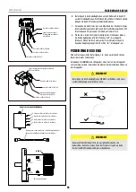
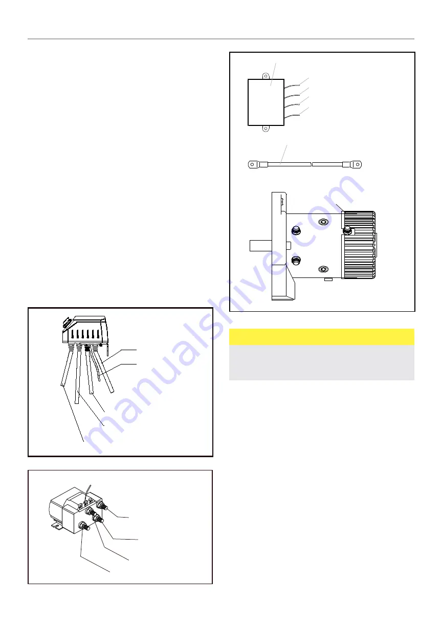
4. Connect the battery and motor leads as the drawing above.
Remember every type of winch is different.
5. Connect the winch motor as detailed below:
Black long wire assembly (connect
the earth terminal on the motor)
Connect to Motor F1 (Yellow)
Connect to Battery Po
Connect to Motor F2 (Red)
Connect to Motor A (Blue)
Black long wire assembly (connect the earth
terminal on the motor)
Connect to motor F2 (Red)
Connect to Motor F1 (Yellow)
Red long wire assembly. Connect to
battery po
Connect to Motor A (Blue)
WIRELESS SWITCH RECEIVER
White wire - connect to relay J3
Yellow wire - connect to relay J1
Red wire - connect to relay J(+)
Black wire - connect to relay J2
Red (F2)
Blue (A)
Yellow (F1)
Black wire assembly - connect to motor’s earthing terminal
and battery negative -
Motor’s earthing terminal
MOTOR
CAUTION
Batteries contain gases which are flammable and explosive. Wear eye
protection during installation and remove all jewelry. Do not lean over
battery while making connections.
6. Assemble the Clevis Hook to the cable. Take off the pin from the
Clevis Hook, connect the Clevis Hook to the cable and mount the pin
back to the Clevis Hook.
7. Always use the Hand Saver (Optional) when free-spooling and re-
spooling the wire rope. Using the Hand Saver keeps your hands and
fingers away from the rotating drum.
8. Check for proper drum rotation. Pull or turn the clutch knob to the
“OUT” “Disengage” position (Free-spooling). Pull out some cable
from the drum, and then turn the clutch knob to the “IN” “Engage”
position to engage the gears. Press the cable out button on the
remote lead switch. If the drum is turning and releasing cable, then
your connections are accurate. If the drum is turning and collecting
more cable, then reverse the leads on the motor. Repeat and check
rotation.
RIGGING TECHNIQUES
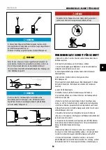
Locate a suitable anchor such as a strong tree trunk or boulder.
ALWAYS use a sling or strap as an anchor point on a object, Never use the
cable or hook as a anchor point attached to an object.


