


4
2600 Emrick Blvd • Bethlehem, PA 18020 • USA • 800-922-0085 • www.warrencontrols.com
SET UP & GENERAL SAFETY
With power applied, preferably, use a signal calibrator to
verify that the valve is fully stroking from one end to the
other as depicted by the travel indicator on the side of
the actuator mounting Pillar and with the proper control
action. Alternately the process controller could be directly
connected to test if it has a ‘Manual-Mode’ of operation
where the controllers output can be manually adjusted from
0% - 100%.
IF THE ACTUATOR IS ONE WITH A DEFINED ‘FAIL-SAFE’
DIRECTION ,THAT CAN BE VERIFIED BY:
1. Using the signal calibrator to move the
actuator position to mid-stroke.
2. Safely disconnecting power at the power
breaker switch and observing the actuator
going to its fail-safe position.
Once these steps are verified you may proceed to
commissioning the control valve. If either of these tests did
not perform as expected, then contact the Warren Controls
factory for further troubleshooting steps.
BASIC SAFETY NOTES:
• Before opening the actuator cover, ensure that the electrical
mains supply voltage is disconnected.
• If operating the actuator with the cover removed for
troubleshooting reasons make sure the wiring terminations
are clearly understood. Contract the Warren Controls factory
for further troubleshooting steps as may be necessary.
• Do NOT attempt to auto-stroke the actuator when the
actuator is not connected to a control valve as it will not
function.
• Do NOT adjust the Manual Override completely downward
when the actuator is not connected to a control valve as this
could permanently damage the actuator.
•If the actuator is removed from the control valve, upon
reinstallation the auto-calibration procedure must be
performed.
CONTROL SIGNAL AND POSITION FEEDBACK CHOICES AND LABEL DESIGNATIONS.
SIGNAL
2-WAY VALVE CLOSED
LABEL
DESIGNATION
3-WAY VALVE
LOWER PORT CLOSED
LABEL
DESIGNATION
4 – 20 mA
@ 4 mA
20 – 4 mA CL
@ 4 mA
20 – 4 mA DN
4 – 20 mA
@ 20 mA
4 – 20 mA CL
@ 20 mA
4 – 20 mA DN
0 – 20 mA
@ 0 mA
20 – 0 mA CL
@ 0 mA
20 – 0 mA DN
0 – 20 mA
@ 20 mA
0 – 20 mA CL
@ 20 mA
0 – 20 mA DN
2 – 10 Vdc
@ 2 Vdc
10 – 2 Vdc CL
@ 2 Vdc
10 – 2 Vdc DN
2 – 10 Vdc
@ 10 Vdc
2 – 10 Vdc CL
@ 10 Vdc
2 – 10 Vdc DN
0 – 10 Vdc
@ 0 Vdc
10 – 0 Vdc CL
@ 0 Vdc
10 – 0 Vdc DN
0 – 10 Vdc
@ 10 Vdc
0 – 10 Vdc CL
@ 10 Vdc
0 – 10 Vdc DN
‘Signal’ as 20-4 CL, to indicate it is a 4 – 20 mA signal and CLOSED at 4 ma. The actuator should be preprogrammed for control
action and which signal is designated. Switching from a milliamp signal to a voltage signal is simply a matter of wiring termination.
Switching whether the control signal is ZERO based or not, or the control action must be done in the software set up. This can
be done on the job site as necessary with the programming umbilical cord option along with a laptop computer that has a USB
connection. If this is required, contact the Warren Controls factory.
Electric installation as well as over-current and over-voltage protection devices must be conform to the standard
DIN IEC 60364-4-41, protection class I resp. protection class III (24VAC/24VDC) and also to the standard DIN IEC
60364-4-44 according to the applied over-voltage category of the actuator.
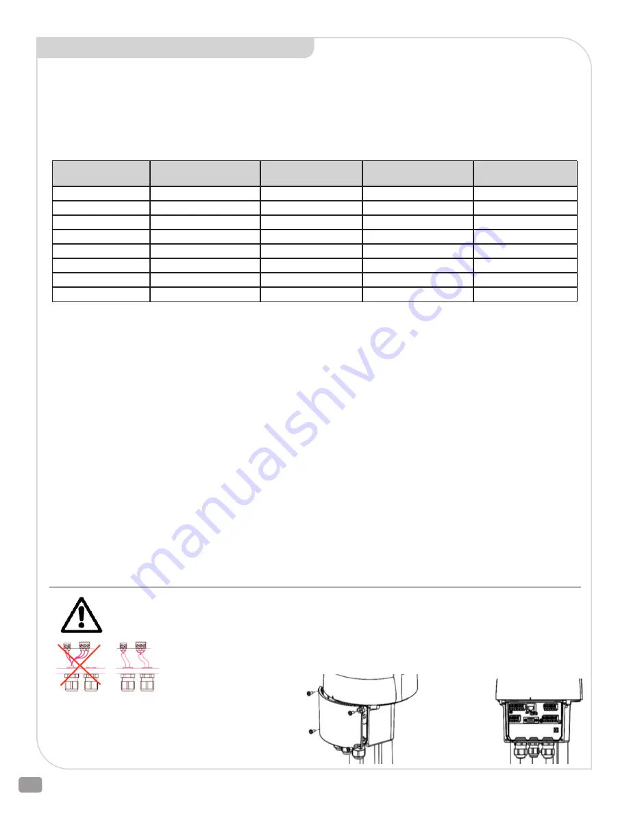
Please protect all of the power supply and control cables in front of the terminals mechanically by
using suitable measures against unintentional loosening.
Remove
connection
terminal cover
Never install the power supply and the control cables
together in one conduit but instead please always use
two different conduit.


