


COMBO-401 i/501 i
OPERATOR’S MANUAL
6
I
nput Power conditions
Power supply : 380-440VAC
The fluctuation range of frequency:
<
±1%
The imbalance rate of three-phase voltage :
<
±5%
While using engine generator, the output power should be two times larger than the rated input power of
the welding power source and compensation coil is needed.
Installation diagram
Connection between welding equipment s and other equipment's (Please refer to the Figure 1).
1.8
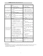
Components name and Function Introductions
(Please refer to the Figure 2)
1.
Voltage meter:
to indicate the actual welding voltage
2.
Current meter:
to indicate the actual welding current
3.
Current adjustment knob:
When switch 10 is placed on the manual welding position, this knob can
adjust the manual welding current. When switch 10 is placed in the gas-shield welding position, this
knob can adjust the gas-shield welding current.
4.
Crater voltage adjustment knob:
adjust the crater voltage.
5.
Arc characteristic adjustment knob:
While used as gas-shield welding, it is to adjust and control
the current changing rate in different duration of the melt drop transfer in the welding process. It will
directly influence arc’s soft and rigid characteristics, quantity of spatter, shaping of welding seam and
the stability of arc. It is advised to use standard characteristic. Adjust it to the soft characteristic while
doing as small criterion welding, and adjust it to the rigid characteristic while doing as middle and
large criterion welding. (
Note: the softer arc, the less spatter, vice versa
.)
6.
Under voltage indicator lamp:
When the distribution voltage is lower than 320VAC, it lights, and
the output current will be cut automatically. After the voltage is back to normal, the machine will
work again.
7.
Over heat indicator lamp:
If it runs beyond excess of its rated duty cycle, or in a high temperature
environment, the thermal sensor’s temperature achieves 75
℃
±5
℃
, the heat protection circuit will
work, and the heat indicator LED will glow, the output current will be cut off. Wait until the machine
cool down and LED turned off, you can restart the machine after that. If the entrance of the gas path
is jammed or the fan doesn’t work, the LED will also glow.
8.
Power source indicator lamp:
As soon as the machine start, it lights.
9.
Welding mode selection switch:
It is to switch the welding process from manual welding to
gas-shield welding.
10. Welding wire diameter selection switch:
It is to switch the standard welding wire’s diameter to
adopt the machine. It is actually to choose the suitable welding program. Turn the switch to the
diameter matched with the welding wire.
11. Welding wire type selection switch:
It is to switch the standard welding wire’s type to adopt the
machine. Turn it to the solid position while using solid welding wire; turn it to the flux-cored position
while using flux-cored welding wire.
12. Crater mode selection switch
:
:
:
:
It is to determine whether fill the arc holes at the end of welding. That
means to determine whether use crater function or not.
13. Gas-supply selection switch
:
:
:
:
To check gas flow, turn it to "checking" position; to weld, turn it to
"welding" position.
14.
Power overload protection switch:
To cut off power and protect the machine in fault condition, it is
only used for protection, you should use other power switch while installing.
15.
Control signal interface:
Output interface of arc striking, to control automatic welding equipments.
The rated control load ability is 3A/250VAC or 3A/30VDC.(This interface is optional)


