


COMBO-401 i/501 i
OPERATOR’S MANUAL
10
Turn on the power switch of distribution box.
Turn the welding machine switch to the manual welding model.
Before welding, make sure the output terminal of the welding machine is connected to the welding
cable properly according to the section 2.2 above. adjusted welding current by the current adjustment knob on
the panel.
Please use proper personal protection equipment.
4. Directions of the Gas-shielded Welding mode
( Please read this manual carefully and strictly operate according to it
)
)
)
)
4.1 Checking items ,methods and requests & preparations before operation
4.1.1 Wears of safeguards
a) Wear fur gloves and safety shoes to protect the skin and bare parts;
b) Wear a helmet with proper shield filter glass that match with different welding current to protect eyes;
c) There should be ventilation in the welding area to prevent breathing the deleterious gas .
4.1.2 Checking after connection:
a) Check out all the items according to the section 2.3 “Connections of Gas-shielded Welding”, make sure
there’s no error.
b) Check out all the items according to the section 1.6 “Input power condition” to meet all the
requirement.
4.1.3 Operations of the switches & adjustment of gas flow.
First, turn on the welding machine;
Second, select the “gas-shield” mode on welding machine;
Third, select “welding wire’s type ” and the “welding diameter” as per requirement by respective switch to
meet the type and diameter of welding wire;
Fourth, turn the “Gas-supply” switch to “check” position;
Fifth, turn on the gas valve of the cylinder, and then adjust the knob of the flow meter slowly to meet the
value needed;
Sixth, turn the “gas supply” switch to “welding” position.
4.1.4 Installation of the welding wire
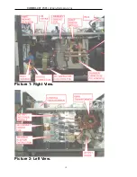
For the identification of operational components please refer to Figure 3 .
Methods and requirements
First, select proper size roller match with feeding wire, install the roller and make sure selected groove
should be outer side ;
Second, pull down the handle of wire feeder, and then lift the press-arm;
Third, install the welding wire reel to the welding wire reel’s axis, adjust the baffle of the welding wire
reel’s axis to be spread
,
screw down the manual nut. The out end of the wire is below. The welding wire will
comes out at clockwise rotation;
Fourth, let welding wire go through the wire rectification wheel (or guide pipe), wire feeding wheel slot, then
insert into the guide tip;
Fifth, press the welding wire with press-arm, and then pull up the handle to press the press-arm,
circumgyrate the handle with suitable strength;
Sixth, check up the tip of welding torch, whose diameter should meet the diameter of the wire;
Seventh, press “manual wire feeding” button on the control box of wire feeder, adjust “welding current
adjustment” knob for a right feeding speed. You can loosen the button until there is 15—20mm wire outside
of welding torch.


