


COMBO-401 i/501 i
OPERATOR’S MANUAL
13
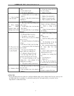
order to avoid worsening the performance or even burning out the machine, there is heat protection on this
series of welding machine. When the inner temperature exceeds the set temperature, the heat protection will
shutdown the machine, the overload indicator LED glows, at this time the machine has no output. Wait until
the temperature is below the set temperature and the overload indicator LED will turned off, the machine
recovers and you can do welding again.
6.2 Crater ON function
Normally there is a small depressing at the end of the weld when welding is done at higher currents. The
depression is called crater, the arc crater are caused because of the arc force and solidification of metal in all
direction. To minimize the crater the machine has crater fill function.
Normally crater fill voltage and current set at 60 to 70 % of the welding voltage and current. When crater is
set ON ( 4 step mode ) the welding voltage and current will automatically switch to lower voltage and
current ( crater voltage and current ) at the end of the welding.
To guaranteed better arc striking every time the wire feeding is normally done at lower speed. When the
torch trigger is pressed irrespective of the current ( wire speed ) set , wire will be fed slowly and it switches
over to the set speed once the arc is struck.
What is burn-back time?
After welding, wire feeder is not stop even if the welding torch switch is shut down because of inertia. So
there will be some more wire drive out from the torch, thus the wire will stick to the workpiece, or it will
cause difficulty in arc striking next time. In order to avoid this , it is necessary to deal with welding machine
operation , so that after releasing the welding torch switch, the output voltage will still exist for a short time
to burn the wire. This process time is burn-back time. This time varies because of differences in welding
conditions, the resistance of welding feeding tube and the length of output cable.
6.3 Examples of welding condition
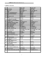
Data in table 1, table 2 is the reference value under the standard condition.
When welding, please correct the values according to work pieces and the welding position to get the right
welding conditions.


