background image

7

Welcome

11

Once setup has been completed the thermostat will display the 

home screen. If you do not press any button for 1 minute the 4iE 

screen will dim and go into standby. To wake the 4iE just tap the 

screen or press the lock icon. 

Press the button on the bottom of the device to put the 

thermostat in/out of standby mode. Hold the button for 3 seconds 

to turn the heating off. 

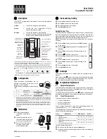
Menu

Time

Date

Air Temperature

Floor Temperature

Target Temperature

Heating Indicator

1
2
3

4

5
6

7

Summary of Contents for 4iE WiFi

Page 1: ...4iE Programmable Thermostat Installation Operating Manual For technical help US 888 927 6333 CA 888 592 7687 warmup com warmup ca ...

Page 2: ...ontents 3 Mounting Positioning 4 Wiring Connections 5 Assembling the 4iE 9 Initial Setup 10 Welcome 11 Programming 12 Energy Monitoring 16 Troubleshooting 17 Settings 18 Important Notices 19 Technical Specifications 21 ...

Page 3: ...qualified and competent electrician and must conform to local electrical code Conduits are only required where it is mandated by state or provincial code Please refer to local electrical code for compliant applications The 4iE and its power supply should be isolated from the mains supply throughout the installation process Pack Contents ...

Page 4: ...e 1 2 Before making any permanent fixtures Warmup recommends identifying your preferred location for the 4iE It should be located in an area with good ventilation It should not be beside a window door in direct sunlight or above another heat generating device e g heater or TV Ensure the distance from your router to the 4iE is not too great This will ensure the wireless connection is not subject to...

Page 5: ...ting Load connected to 4iE Max 15 Amps N B Input voltage 120V Hot Neutral or 240V Hot Hot Device is dual voltage capable L1 LOAD L2 L1 LINE L2 1 2 3 EXT FLOOR SENSOR NO POLARITY L1 LOAD L2 HEATING MAX 3600W 15 Amps L1 LINE L2 POWER SUPPLY L2 LINE HOT 120V SUPPLY WITHOUT GFCI PROTECTION NEUTRAL 120V OR HOT 240V Heater s Max 15A L1 LINE ...

Page 6: ... 240V GFCI PROTECTED SUPPLY 240V COIL SUPPLY N B All heating loads connect to Relay 25 only controlled by 4iE L1 LOAD L2 L1 LINE L2 1 2 3 EXT FLOOR SENSOR NO POLARITY L1 LOAD L2 HEATING MAX 3600W 15 Amps L1 LINE L2 POWER SUPPLY Hot 240V Hot 240V 0 1 8 6 4 2 Heater s Max 25A Heating Load connected to Relay 25 Max 25 Amps ...

Page 7: ...240V Hot 240V L1 LOAD L2 L1 LINE L2 1 2 3 EXT FLOOR SENSOR NO POLARITY L1 LOAD L2 HEATING MAX 3600W 15 Amps L1 LINE L2 POWER SUPPLY 0 1 8 6 4 2 Heater s Max 25A Heater s Max 15A 240V COIL SUPPLY N B Heating loads connect to Relay 25 and 4iE Relay 25 Max load 25A 4iE Max load 15A Total Max load 40A Heating Load connected to 4iE and Relay 25 Max 40 Amps ...

Page 8: ...wo 4iE s one being the master and the other being the relay slave Only one floor sensor is required wired into terminals 1 2 of the Master 4iE Wiring Connections Use low voltage electrical cables to link terminals 2 3 of the Master and Relay Thermostat Setup Settings Adv settings Heater setting Ext output NOTE Set the relay 4iE to relay first ...

Page 9: ...4iE Step 3 Reattach 4iE Face Reattach the 4iE face to the Back Plate and tighten both screws to secure You may now restore power to the thermostat and begin setup 1 7 Assembling the 4iE 9 ...

Page 10: ...r 4iE Display brightness change the screen brightness for normal use and standby Audio feedback turn the click sound on off Heating target control your heating using the floor air sensor Heating limits set the temperature limits for your floor type User Defined lets you set custom limits Tariff settings select single or standard low energy tariff Set a program select between custom preset or fixed...

Page 11: ... screen will dim and go into standby To wake the 4iE just tap the screen or press the lock icon Press the button on the bottom of the device to put the thermostat in out of standby mode Hold the button for 3 seconds to turn the heating off Menu Time Date Air Temperature Floor Temperature Target Temperature Heating Indicator 1 2 3 4 5 6 7 ...

Page 12: ...he setback temperature is defaulted to 61 F To alter the setback Press Menu Program Set setback temperature Setting a Custom Program allows you to set comfort temperatures at set times throughout the day cancel accept help saturday sunday monday tuesday friday thursday wednesday cancel delete accept period 1 start 06 00 08 00 temp end 70 F back set custom program select preset program set fixed tem...

Page 13: ...Temp Mon Fri 06 00 08 00 19 00 23 00 72 F 61 F 68 F 61 F 18 00 21 30 70 F 61 F 06 00 08 00 20 00 23 00 70 F 61 F 68 F 61 F 06 00 08 00 18 00 22 00 70 F 61 F 70 F 61 F Sat Sun 07 00 11 00 18 00 23 00 72 F 61 F 68 F 61 F 08 00 21 30 70 F 61 F 06 00 08 00 20 00 23 00 70 F 61 F 68 F 61 F 07 00 11 00 18 00 22 00 70 F 61 F 70 F 61 F cancel help accept monday tuesday wednesday thursday friday saturday su...

Page 14: ...ure duration of override and press accept Set a fixed temperature for the thermostat to reach and maintain until you revert back to program mode or switch the heating off Set a temperature you would like the thermostat to reach and the length of time you want this override to last back accept override target 61 F until 15min back set custom program select preset program set fixed temperature back a...

Page 15: ... and press accept Select Frost Protect to set your heating to a constant 45 F to protect your home from frost Press menu Temperature Frost protection Holiday Mode allows you to override your schedule with a lower fixed temperature over a set time to save energy back program start date off off holiday mode end date back next start date 12 00 2016 01 jan back next end date 12 00 2016 02 jan back accep...

Page 16: ...of your system and the cost per kilowatt hour charged by your energy provider The 4iE will use this information to calculate the running cost of your system When you ve set up the Energy Monitor you can view the estimated usage or cost over a selected time period If you have a standard low energy tariff the amount and cost of energy used during the standard period will be displayed in dark green a...

Page 17: ...nce of the floor sensor should measure between 8K ohms and 12K ohms If the electrician finds a fault and the 4iE is in the room to be heated then it can be set into Air Mode Air Mode only suitable for tiled floors if floor sensor has been damaged 1 The 4iE Early Start function is on This means that the heating will come on early to achieve the set temperature at the set time 1 Delicate floor cover...

Page 18: ... normal use and standby Lock Set a lock code Audio Feedback turn the click sound on off Network Choose a WiFi network Heater Settings Heating Limits Set the temperature limits for your floor type User Defined lets you set custom limits Regulator Controls the heating in 10 minute cycles The number you enter is the number of minutes in a 10 minute cycle that the heating will be on Ext Output T his a...

Page 19: ...lation This equipment generates uses and can radiate radio frequency energy and if not installed and used in accordance with the instructions may cause harmful interference to radio communications However there is no guarantee that interference will not occur in a particular installation If this equipment does cause harmful interference to radio or television reception which can be determined by t...

Page 20: ...ature is used to detect any leakage of current from your heating system During a ground fault the two lines of the load will be cut off Once your thermostat is installed and connected to a power supply you can test the GFCI function by increasing the set temperature until heating is on the heating up icon will be illuminated and pressing the TEST button If your test is successful you will see the ...

Page 21: ...in GFCI Class A GFCI with 5mA trip level Sensors Air Floor Ambient Sensor Type NTC10k 3m Long Can Be Extended To 50m Max Load 15A 3600W Installation Depth 2 3 4 deep double gang box recommended Compatibility Electric Hydronic Underfloor Heating up to 16A Warranty 3 Year with optional Lifetime Upgrade Approvals ETL ...

Page 22: ...Notes 22 ...

Page 23: ...Notes 23 ...

Page 24: ...oes not cover removal or re installation costs and shall not apply if it is shown by Warmup that the defect or malfunction was caused by failure to follow the instruction manuals incorrect installation or damage which occurred while the product was in the possession of a consumer Warmup s sole responsibility shall be to repair or replace the product within the terms stated above WARMUP SHALL NOT B...

Reviews: