


14 June 2016
Due to continued product improvement, Warmington Ind LTD reserves the right to change product specifications without prior notification.
All Dimension are in mm………….Copyright ©
6
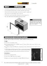
APPLYING THE VERMICULITE :
(Course—must be larger than the burner plates holes so not to block them)
Apply with care a thin layer of Vermiculite over the Burner, just enough to cover the Burner Tray only .
NOTE: If the burner flame is uneven, the Vermiculite may need to be changed or sifted to remove the smaller pieces that can block the burners
holes. The smaller pieces can ,cause uneven burn and the unit to run dirty.
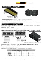
COALS AND LOGS (To be set by Gasfitter)
VERMICULITE (COURSE) (To be set by Gasfitter)
Total Coals
Bottom
Top
Bottom
Top
Model
Total
SG EG 700
6
5
2
2
22
8
6
2
2
SG EG 780
28
SG EG 900
10
9
2
2
38
SG EG 1100
11
10
2
2
42
Number of Coals per Row
Number of Rows
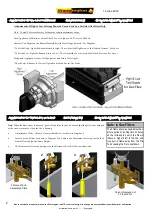
2 : Top Row
Slide R & LH Grate
Pins into Holes located
on the Burner Side
plates .
1 : Bottom Row
Gloves should be worn when handling Ceramic Fibre Coals & Logs : care needs to be taken when handling Coals & Logs , Due to the Carbon on the
Coals can stain the surroundings.
HELPFUL HINTS : When Hot use Metal Tongs
.
Apply a thin layer of Vermiculite over the Burner , just enough to cover the Burner Tray only as shown above.
1 : Bottom Row
: Assemble 2 Bottom Rows of Coals onto the Vermiculite Base .
2 : Top Row
: Assemble 2 Top Rows of Coals onto the Bottom Row .
Each Coal randomly positioned with the Torn (roughest) Face Outward .
Ensure Coal positioning does not directly block the 3 Flame Pilot .
The placement of the Coals & Logs may vary to make an even Flame Pattern .
Logs and Twigs may be scattered to achieve best Visual Effect .
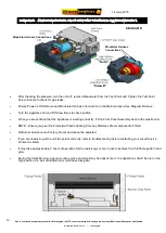
Fit Burner Grate by sliding R & L Side Metal Pins on Grate, into Holes Located on Burner Side Plates , as shown below .
Model SG780 Shown: Total number of coals will vary per model.
General Coal orientation fro optimum effect.


