


14 June 2016
Due to continued product improvement, Warmington Ind LTD reserves the right to change product specifications without prior notification.
All Dimension are in mm………….Copyright ©
4
STEP 5 : FIT EG ELECTRONICS ETC INTO FIREBOX
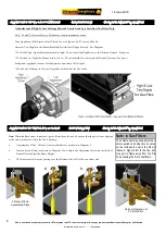
STEP 5 : Fit EG Electronics etc into Firebox .
Once EG assembly is fitted in place as shown above , screw RH Side Burner Plate down using self tapping
screws supplied . Do not screw down Control Valve & Circuit Board Assembly until Gas Fitting & any Electrical
work has been carried , both Gas Fitting & Electrical work should be carried out at this stage .
3 Speed Fan Wire .
Main Power
Supply Wire .
EG 845 Control Valve Cover .
Main Circuit Board .
Screw Down
RH Side Burner Plate
using self tapping
screws supplied .
STEP 6 : RE-ASSEMBLE EG COMPONENTS COVERS & MAIN BURNER ASSEMBLY INTO FIREBOX
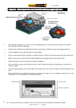
STEP 6 : Re-assemble Covers etc into Firebox
First screw down Control Valve Cover & 2X Main Circuit Board Covers in place as shown above , then fit Main
Burner Assembly onto the RH Burner Side Plate previously fitted in step 5 (take care to avoid damaging Gas
Injector Jets on RH Burner Side Plate) . Once this is complete fit the Burner Front Caste Grate to the Main
Burner Assembly with the locating pins on each side of the Grate , note that the Grate Door has holes punched
in it where the Receiver Circuit Board attaches to , attach Receiver Circuit Board in place to complete the FP-
SG to FP-EG burner change over . For Coal/Logs Setup ,Testing & Commissioning see pages 5 to 14 .
Main Circuit Board Covers .
Receiver Circuit
Board .
EG Front Caste Grate .


