


14 June 2016
Due to continued product improvement, Warmington Ind LTD reserves the right to change product specifications without prior notification.
All Dimension are in mm………….Copyright ©
3
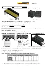
STEP 3 a: Dis-assemble Packaged parts as shown .
Dis-assemble Main Burner Assembly from RH Side Burner Plate then remove the
EG 845 Control Valve Cover & EG Main Circuit Board Control Cover . Take care to
avoid any kinking of the Copper Pipe work . You can also disconnect the Blue Cable
from the Receiver Circuit Board at the back for ease of Installation
RH Side Burner Plate .
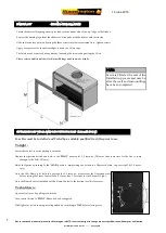
STEP 3b : Dis-assembled Components ready for Installation .
The dis-assembled Components ready for Installation
should look as shown below . The Main Power Supply
Wire & Fan Wire will need to be connected to the
Wires previously located inside the Firebox in Step 2 ,
all Electrical & Gas Fitting work should be carried out
by Certified Tradesman .
Control Valve Cover .
Circuit Board Control Cover .
3 Flame Igniter .
Main Burner Assembly .
Main Circuit Board .
Receiver Circuit
Board .
EG 845 Control Valve .
Main Power
Supply Wire .
3 Speed Fan Wire .
Main Power
Supply Wire .
3 Speed Fan Wire .
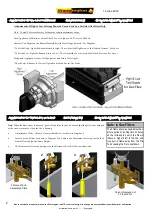
STEP 4 : FIT EG ELECTRONICS ETC INTO FIREBOX
STEP 4 : Fit EG Electronics etc in position through RH Side Breakout Panel .
Fit previously dis-assembled components as shown above into Firebox by feeding the Main Circuit Board in first
through the RH Side Broken Out Panel as indicated above followed by the EG 845 Control Valve Assembly & RH
Side Burner Plate . Once in position inside the Firebox ensure the Main Power Supply Wire & 3 Speed Fan Wire
are accessible to be connected . Once connected push the wires back under the Broken Out Panel area to keep
away from direct heat , also keep clear from the 3 Speed Fan area .
3 Speed Fan Wire .
Main Power
Supply Wire .
3 Speed Fan Wire .
Main Power
Supply Wire .
EG 845 Control Valve .
Main Circuit Board .
RH Side Burner Plate .
STEP 3 : DIS-ASSEMBLE PACKAGED ELECTRONICS & BURNER


