background image

6.6.3  Hydraulic Oil, Changing

 CAUTION!

Risk of burns to exposed skin. 

Hydraulic oil becomes hot during 

operation. Hoses, lines, and other 

parts become hot as well. Wait for 

the oil and components to cool 

before starting any maintenance or 

inspection work.

W028

Change the hydraulic oil in the reservoir at 

100 hours 

of 

operation or annually. 

IMPORTANT!  Change the return filter on the tank at the 
same time.

• 

Hydraulic oil type: 

Dexron III ATF. 

• 

Hydraulic oil tank capacity: 

4.6 US gal (17.5 L).

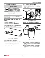
The reservoir drain plug is located on the underside of the tank. 
A 3/8" Allen wrench is required to remove it.

00539

3/8"

Fig.  45 – 

Hydraulic Tank Drain Plug

1. 

Have a drain pan ready of suitable capacity.

2. 

Clean the area around drain and remove the drain plug.

3. 

Allow the oil to fully drain, then flush the tank. Dispose of 
used oil in an environmentally acceptable method.

4. 

Re-install the drain plug.

6.6.4  Hydraulic Filter, Changing

1. 

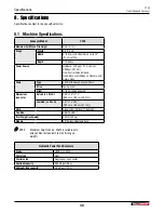
The hydraulic system return filter is the spin-on type. 
Remove the filter and dispose of it in an environmentally 
friendly manner.

00537

Fig.  46 – 

Hydraulic Oil Filter

2. 

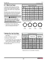
Wet around the seal on the new filter with clean oil.

00538

Fig.  47 – 

Oil the Seal

3. 

Turn the new filter on by hand until it is snug, then tighten 
another 1/4 turn. Wipe off any oil residue on the filter and 
filter head.

4. 

Fill the reservoir with clean, new oil. Verify the oil level 
using the dipstick. The oil level should be at the upper 
mark.

 CT24

Trailer Firewood Conveyor

Service and Maintenance

37

Summary of Contents for CT24

Page 1: ...OPERATOR S MANUAL Trailer Firewood Conveyor CT24 S N CT244 Up CT24 Part Number Z97163_En Rev Feb 2022...

Page 2: ...the split stack pile builds up Safe efficient and trouble free operation Wallenstein products requires that anyone using or maintaining the machine reads and understands the Safety Operation Maintenan...

Page 3: ...6 4 Conveyor Setup 17 5 Operating Instructions 19 5 1 Break in Period 19 5 2 Pre Operation Checklist 19 5 3 Setting Conveyor Speed 20 5 4 Conveyor Height Adjusting 20 5 5 Conveyor Angle Indicator 21 5...

Page 4: ...Province ZIP Postal Code Phone Number Contact Name Model Serial Number Delivery date I have thoroughly instructed the buyer on the equipment care adjustments safe operation applicable warranty policy...

Page 5: ...STANDARDS PRESCRIBED UNDER THE CANADIAN MOTOR SAFTEY REGULATIONS IN EFFECT ON THE DATE OF MANUFACTURE CE VEHICLE EST CONFORME A TOUTES LES NORMES QUI LUI SONT APPLICABLES EN VERTU DU REGLEMENT SUR LA...

Page 6: ...chine model and serial number and other important information VIN NLV MODEL Manufactured by Wallenstein Equipment Inc 7201 Line 86 Wallenstein ON N0B2S0 Canada TYPE OF VEHICLE TYPE DE VEHICLE TRA REM...

Page 7: ...tuation that if not avoided may result in minor or moderate injury It may also be used to alert against unsafe practices IMPORTANT To avoid confusing equipment protection with personal safety messages...

Page 8: ...onnel who will be operating or performing maintenance Do not expect a person who does not understand operation and safety instructions to use the machine Untrained operators are not qualified and can...

Page 9: ...e of the hoisting winch could cause the conveyor to lower unexpectedly Do not climb on the conveyor If maintenance or other work is required avoid the risk of falling off by lowering it 2 6 Equipment...

Page 10: ...ream of hydraulic fluid Serious infection or toxic reaction can develop from hydraulic fluid piercing the skin surface Do not attempt any makeshift repairs to the hydraulic lines fittings or hoses by...

Page 11: ...shows the message how to avoid the hazard Hazard How to avoid the hazard Practicing good safety means becoming familiar with safety signs and warnings and being aware of the situations that require al...

Page 12: ...r caught in drive chain resulting in serious injury Keeps hands clear of this area 3 Warning Risk of hands being crushed in this area Keep hands clear of all moving parts 4 Warning Risk of hydraulic f...

Page 13: ...f 1986 IMPORTANT If parts are replaced that have safety signs on them new signs must be applied Safety signs must always be replaced if they become damaged are removed or become illegible Safety signs...

Page 14: ...ch information has been reviewed Review this information annually before the season start up Make these periodic reviews of safety and operation a standard practice for all equipment An untrained oper...

Page 15: ...hine 3 3 Job Site Familiarization It is the responsibility of the operator to be thoroughly familiar with the work site prior to starting Doing so can prevent the chance of problems or accidents 3 4 E...

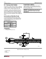
Page 16: ...ts 1 Conveyor Hopper 2 Conveyor Chain 3 Chain Cleats 4 Conveyor Trough 5 Hydraulic Motor 6 Folding Frame Upper 7 Hand Winch 8 Winch Cable 9 Toplink 10 Folding Frame Lower 11 Wheels 12 Flow Control val...

Page 17: ...the conveyor is raised 00452 Fig 5 Hitch Lock Pin Fig 6 Decal on hitch plate 4 Anchor the conveyor under the processor discharge by driving a 1 2 12 mm steel rod not supplied through the hole in the...

Page 18: ...ap is the pressure line and black is return to tank 00480 Fig 10 Hose Connections If connecting the conveyor to the Wallenstein WP1624 wood processor an auxiliary valve kit is required to control the...

Page 19: ...equired Make sure equipment is working as designed and in good repair If conveyor is off loading into a truck or trailer plan access for this equipment Check that personal protection equipment includi...

Page 20: ...olled oil flow exits through the CF port to power the conveyor motor Excess flow not required is diverted to the EX port and returns to tank Return from the conveyor motor is connected at the EX port...

Page 21: ...or sideways when the split wood stack height is up to the conveyor or approaching the wheels Unpin and rotate the wheels to swing the conveyor Remove lynch pin then pull the pin and rotate the wheel R...

Page 22: ...wheels See page 31 for instructions on wheel rotation Push the conveyor to the new position Block the wheels Check the position of the hopper end of the conveyor Make sure it is placed so split wood...

Page 23: ...tioned and bolted to the conveyor frame based on the measurements in the following table Measure from the front of the wheel base frame to the center of the axle measurement X Measurement X No Power P...

Page 24: ...contained powered by a Honda GX200 engine coupled to a pump with an oil reservoir hoses return filter and control valve 1 4 2 3 5 7 8 10 11 12 9 6 00535 Fig 41 Accessory Hydraulic Power Pack 1 Contro...

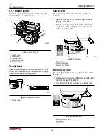
Page 25: ...es the choke valve in the carburetor Place the choke lever in the CLOSED position 3 when starting a cold engine Move the choke lever to the OPEN position 2 after the engine starts When restarting a wa...

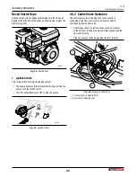
Page 26: ...wise to OFF to stop the engine 00187 Fig 25 Ignition Switch 5 9 2 Control Valve Operation The control valve starts and stops the conveyor and is connected to the flow control valve Conveyor speed is c...

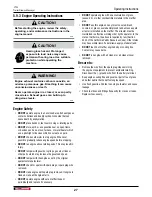
Page 27: ...t by the original equipment manufacturer DO NOT check for spark with spark plug or spark plug wire removed DO NOT crank engine with spark plug removed If engine is flooded crank until engine starts DO...

Page 28: ...omponents away W027 DO NOT refuel indoors where area is not well ventilated DO NOT refuel while engine is running Allow engine to cool for five minutes before refueling Store fuel in approved safety c...

Page 29: ...ipstick Add oil as required IMPORTANT Do not operate machine if oil level is low Damage to the pump and other components can occur IMPORTANT Hydraulic oil quality should be inspected every 50 hours If...

Page 30: ...nd otherwise ready to run 1 Slide the fuel valve lever toward the block 2 to turn fuel ON 00190 2 1 3 Fig 31 Fuel Valve Lever 1 Fuel Shut off Valve Lever 2 ON Position 3 OFF Position 2 If the engine i...

Page 31: ...down for rough terrain and cornering Do not transport or move the conveyor with the engine running if equipped Make sure the conveyor is hitched positively to the towing vehicle and a retainer is use...

Page 32: ...rn the winch handle counterclockwise No clicking sound is heard because the brake system is activated 00448 Fig 38 Lowering Conveyor Lock the hitch before towing 00459 Fig 39 Hitch Lock Pin To adjust...

Page 33: ...if equipped Add fuel stabilizer to the fuel tank 3 Make sure the hose ends are capped and stored 4 Grease conveyor drive bearings one grease gun shot for each bearing See page 35 5 Select an area tha...

Page 34: ...age caused by using non approved parts or accessories Make sure all safety shields and devices are re installed after a maintenance or service procedure is finished Do not use gasoline or diesel fuel...

Page 35: ...Chain Tension Adjusting The conveyor chain can stretch a slight amount and can require occasional adjustment Care must be taken the chain is not over adjusted as this adds pretension into the chain a...

Page 36: ...to the engine manufacturer s manual for maintenance and service information 2 Engine Fuel The power pack engine is certified to operate on unleaded gasoline with a pump octane rating of 86 or higher...

Page 37: ...Have a drain pan ready of suitable capacity 2 Clean the area around drain and remove the drain plug 3 Allow the oil to fully drain then flush the tank Dispose of used oil in an environmentally accepta...

Page 38: ...00536 3 2 1 Fig 48 Hydraulic Oil Level 1 Full Oil Level Mark 2 Low Oil Level Mark 3 Oil Level Dipstick Service and Maintenance CT24 Trailer Firewood Conveyor 38...

Page 39: ...distance between axle sprockets Excessively worn sprocket The chain and sprocket do not match Replace the chain and or sprocket with the correct sized part Unusual noises Excessive wear in the chain...

Page 40: ...op Sprocket Flight 2 5 cm High Serrated Dimensions see note Raised L x W x H 260 x 74 x 174 660 cm x 188 cm x 442 cm Lowered L x W x H 307 x 74 x 83 780 cm x 188 cm x 211 cm Hitch Clevis Hitch Optiona...

Page 41: ...identified by their head markings Imperial Bolt Torque Specifications Bolt Diameter Torque Value SAE Gr 2 SAE Gr 5 SAE Gr 8 lbf ft N m lbf ft N m lbf ft N m 1 4 6 8 9 12 12 17 5 16 10 13 19 25 27 36 3...

Page 42: ...m 20 25 26 32 5 35 40 45 5 52 50 60 65 78 14 lbf ft N m 20 25 26 32 5 50 60 65 78 90 120 117 156 15 lbf ft N m 20 25 26 32 5 50 60 65 78 90 120 117 156 16 lbf ft N m 20 25 26 32 5 50 60 65 78 90 120...

Page 43: ...does not cover the following 1 Normal maintenance or adjustments 2 Normal replacement of wearable and service parts 3 Consequen al damage indirect damage or loss of pro ts 4 Damages resul ng from Misu...

Page 44: ...ration Checklist 19 Rotate Wheels 22 Conveyor Setup 17 Conveyor Speed 20 Conveyor Tongue Weight 23 D Decals on the machine types 6 E Engine Controls Choke Lever 25 Fuel Shut off Valve 25 Ignition Swit...

Page 45: ...Damaged Safety Signs 13 Safety Alert Symbol 7 Safety Training 34 Signal Words 7 Safety Alert Symbol 7 Safety Notice Decals 6 Safety Rules 8 Safety Sign Locations 11 Safety Signs Safety Sign Locations...

Page 46: ......

Page 47: ......

Page 48: ...www wallensteinequipment com...

Reviews: