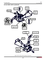
Wallenstein BX36S Operating Manual Download Page 11

BX36S

3PH Self-feed Chipper

Safety

11

• 

Never consume alcoholic beverages or use 

drugs which can impair alertness or coordination 

while operating this equipment. Consult your 

doctor about operating this machine while taking 

prescription medications.

• 

Do not allow riders on this machine at any time. 

There is no safe place for any riders.

• 

Never allow children or unauthorized people to 

operate or be around this machine.

• 

Keep children and persons unfamiliar with 

machine operation away. The operator should be 

a responsible, physically able person trained in 

equipment operation. If the elderly are assisting 

with work, their physical limitations need to be 

recognized and accommodated.

• 

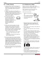
Do not reach into rotor or feed hopper openings 

when the engine is running. Install and secure 

access covers before starting engine.

• 

Keep the working area clean and free of debris to 

prevent tripping. Operate only on level ground.

• 

Do not point discharge at people, animals or 

buildings. Rotor can expel wood chips fast enough 

to cause injury.

• 

Do not move or transport chipper when the rotor is 

turning.

• 

Do not exceed a safe travel speed when 

transporting.

• 

Keep chipper resting on the ground during 

operation. Using the chipper while raised off the 

ground is dangerous and will result in damage to 

the machine, and potential personal injury.

• 

Never have the exit chute pointing towards the 

hopper or operator working area. Chips can come 

out of the chute with enough force to cause injury.

6.8  Equipment Safety Guidelines

Safety of the operator and bystanders is one of the 

main concerns in designing and developing equipment. 

However, every year many accidents occur which 

could have been avoided by a few seconds of thought 

and a more careful approach to handling equipment. 

You, the operator, can avoid many accidents by 

observing the following precautions in this section. 

To avoid personal injury or death, study the following 

precautions and insist those working with you, or for 

you to follow them.

In order to provide a better view, certain photographs 

or illustrations in this manual may show an assembly 

with a safety shield removed. However, equipment 

should never be used in this condition. Keep all shields 

in place. If shield removal becomes necessary for 

repairs, replace the shield prior to use.
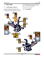
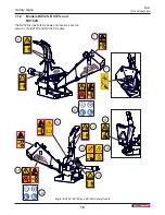
1. 

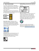
Replace any safety sign or instruction sign that is 

not readable or is missing. Location of such safety 

signs is indicated in this manual.

2. 

Do not modify the equipment in any way. 

Unauthorized modification may result in serious 

injury or death and may impair the function and life 

of the equipment.

3. 

In addition to the design and configuration of this 

implement, including Safety Signs and Safety 

Equipment, hazard control and accident prevention 

are dependent upon the awareness, concern, 

prudence, and proper training of personnel 

involved in the operation, transport, maintenance, 

and storage of the machine. 

Refer also to Safety 

Messages and operation instruction in each of the 

appropriate sections of the tractor and machine 

manuals. Pay close attention to the Safety Signs 

affixed to the tractor and the machine.

4. 

Never exceed the limits of a piece of machinery. 

If its ability to do a job, or to do so safely is in 

question – 

DO NOT TRY IT

.

.

Summary of Contents for BX36S

Page 1: ...OPERATOR S MANUAL 3PHSelf feedChipper BX36S BX52S BX72S BX102S...

Page 2: ...ooting information contained within the Operator s Manual This manual covers all variations of the Wallenstein 3 Point Hitch Wood Chipper BX Series Your particular model may vary from the illustration...

Page 3: ...ents 19 9 PTO Shaft Connection 21 9 1 Determine Correct PTO Shaft Length 21 10 Attaching Chipper to Tractor 22 10 1 Procedure 22 11 Controls 24 11 1 Discharge Chute 24 11 2 Hood Deflector 25 12 Operat...

Page 4: ...structions in the owner s manual with the label illustrated alongside Informative Labels are generally pictorial with a white background and can vary to the number of panels The label will illustrate...

Page 5: ...ngine manufacturer s website For service contact your local engine dealer Under no circumstances will the manufacturer be liable for any consequential damage or expense of any kind including loss the...

Page 6: ...at http www wallensteinequipment com This form must be filled out by the dealer and signed by both the dealer and the customer at the time of delivery _________________________________________ Custome...

Page 7: ...oduct when ordering parts or requesting service or other information The Serial Number Plate location is shown in the illustration Please record the product Model and Serial Number in the space provid...

Page 8: ...purposes cannot be guarded WARNING Indicates a potentially hazardous situation that if not avoided COULD result in death or serious injury and includes hazards that are exposed when guards are remove...

Page 9: ...ructions in the manual and follow them Most accidents can be avoided The most important safety device on this equipment is a SAFE operator DO review safety related items annually with all personnel wh...

Page 10: ...gned this 3 Point Hitch Wood Chipper to be used with all its safety equipment properly attached to minimize the chance of accidents Close and secure rotor cover before operating Close and secure all g...

Page 11: ...operator and bystanders is one of the main concerns in designing and developing equipment However every year many accidents occur which could have been avoided by a few seconds of thought and a more c...

Page 12: ...ble serious injury or death If the elderly are assisting with the work their physical limitations need to be recognized and accommodated 6 Know your controls and how to stop the machine and the tracto...

Page 13: ...h for traffic when operating near or crossing roadways Never allow riders on the machine 6 12 Sign Off Form Wallenstein follows the general Safety Standards specified by the American Society of Agricu...

Page 14: ...the illustrations that follow Good safety requires that you familiarize yourself with the various safety signs the type of warning and the area or particular function related to that area that require...

Page 15: ...nd operating instructions in the manual Read and understand ALL safety labels located on the machine The most important safety device on this equipment is an informed SAFE operator BX36S Safety Sign E...

Page 16: ...16 Z94242 7 1 2 Models BX52S BX72S and BX102S The BX52S is illustrated Labels and locations are the same for the BX72S and BX102S models 75mm 3 0 Z94232 75mm 3 0 Z94232 1 2 2 8 6 7 3 5 3 9 10 9 4 Fig...

Page 17: ...an informed SAFE operator Caution 6 Pinch point hazard When lowering or raising the hopper into position be aware of pinch points and keep clear of them to avoid injury Caution 4 When performing any...

Page 18: ...rs are designed to chip and chop scrap lumber small trees brush limbs and other wood debris The chipped material is fine enough to be composted or used in a variety of ways It is the responsibility of...

Page 19: ...mponent descriptions here are used throughout the manual to explain function and safety For a detailed parts breakdown see your dealer or visit the Wallenstein website to download the Parts Manual Blo...

Page 20: ...scharge Chute Adjustable Ski Discharge Latch Handle Manual Tube PTO Shaft Lower Link Pins Top Link Deflector Adjustor Upper Rotor Housing Folding Feed Hopper Ledger Blade Twig Breaker Rotor Lock Feed...

Page 21: ...ctor see section 4 6 but do not attach the drive line 2 Raise the machine until the input shaft is level with the tractor PTO shaft 3 Measure the dimension A between the locking grooves on the tractor...

Page 22: ...point hitch only and is also quick hitch and iMatch compatible For maximum life and safety connect PTO shaft with machine as level as possible when the chipper is in the lowered working position NOTE...

Page 23: ...p with the link pins 9 Engage the tractor park lock brake dismount the tractor make any final adjustments and slide the left and right lower arm holes onto the link pins 10 Install the retainers on th...

Page 24: ...Chute Model BX36S The discharge chute is designed with a spring loaded latch handle that allows the chute to be positioned 360 then locked into position with the latch 1 Lift the latch handle until th...

Page 25: ...flector on the end of the chute to direct the chips exactly where desired 1 Lift and push forward the adjustor grip handle and move the deflector into position as required 2 Lock the deflector into po...

Page 26: ...in position Set up the machine see page 26 Each person must wear appropriate Personal Protective Equipment PPE whenever operating the Wood Chipper or working in the vicinity The PPE list includes but...

Page 27: ...e ground is dangerous and will result in damage to the machine 12 3 Adjust Ski Height The ski can be adjusted up to 6 0 in 150 mm if required to help align the PTO when attaching the chipper to the tr...

Page 28: ...lated safety precautions outlined in this section A pre operation checklist is provided for the operator It is important for both the personal safety and maintaining good mechanical condition that thi...

Page 29: ...ing engine and resuming work 12 9 Chipping Operation BX Series Wood Chippers are strong rugged machines They are built to provide consistent chipping of logs CAUTION Be aware Rotor continues to turn f...

Page 30: ...r the area of all bystanders 3 Visually inspect and ensure all material is out and nothing is jammed or wedged between the hopper and the rotor If this does not unplug the chipper or the engine is sto...

Page 31: ...e slow moving vehicle sign is in place and all the lights and reflectors required by the highway authorities are in place Make sure they are clean and functioning properly 4 Check that the tractor is...

Page 32: ...he machine with a pressure washer or water hose to remove all dirt mud or debris 4 Inspect all rotating parts for entangled material Remove all entangled material 5 Run the machine a few minutes to dr...

Page 33: ...pment Periodically tighten all bolts nuts and screws and check that all electrical and fuel connections are properly secured When completing a maintenance or service procedure make sure all safety shi...

Page 34: ...purposes only Never operate machine with guards removed W001 Refer to Maintenance Schedule on page 38 IMPORTANT Grease machine at period shown or hour interval whichever comes first Location Every 8...

Page 35: ...Rotor main shaft front roller flange 5 Hood deflector 6 Discharge chute swivel 7 PTO telescoping section One pump from a hand held grease gun Location Every 100 hours or annually Wash and clean wood...

Page 36: ...te machine with guards removed W001 Refer to Maintenance Schedule on page 38 IMPORTANT Grease machine at period shown or hour interval whichever comes first Location Every 8 hours or daily 1 PTO lubri...

Page 37: ...main shaft front roller flange 6 Hood deflector 7 Discharge chute swivel 8 PTO telescoping section One pump from a hand held grease gun Location Every 100 hours or annually Wash and clean wood chipper...

Page 38: ...l whichever comes first Every 8 hours or Daily Every 50 hours or Annually Every 100 hours or Annually Item Check twig breaker rotor blades ledger blade Check that all fasteners are secure Lubricate hi...

Page 39: ...heck all nuts bolts and screws and ensure they are all properly secured on a regular basis Fig 26 Service Illustration Rotor blades check every 8 hours Blades may need to be changed after 8 10 hours d...

Page 40: ...reassembling the driveline ensure that the driveline is assembled in phase to avoid unnecessary vibration when the machine is running 15 5 Shear Pin The PTO drive line is designed with a shear pin at...

Page 41: ...ended use while in operation The rotor lock pin should be used anytime the rotor housing is open to prevent potential injury Lock Pin Engaged Rotor Hood Open Fig 28 Rotor Lock Pin BX52S BX72S BX102S s...

Page 42: ...rotor slowly and be aware of hand positioning W002 WARNING Machine shown with guards removed for illustrative purposes only Never operate machine with guards removed W001 15 8 1 Changing Rotor Blades...

Page 43: ...ll it down and slightly to the side to clear the axle 3 Rotate the blade and reinstall or replace with new or re sharpened blade 4 Hand tighten the bolts 5 Set the clearance between the ledger and rot...

Page 44: ...lly open the rotor housing 2 Carefully move the rotor so the a rotor blade overlaps the ledger blade 3 Loosen the fasteners and or adjusters and move the ledger away from the rotor blade 4 Insert the...

Page 45: ...knives Ensure machine is off Rotor blade angle wrong improper angle Re sharpen knives to specified angle and check that blade is installed properly Ensure machine is off Obstructed discharge Clear deb...

Page 46: ...hardened reversible 4 bolt hardened reversible 3 bolt hardened reversible Rotor Weight 96 lb 43 5 kg 125 lb 56 7 kg 175 lb 79 3 kg 400 lb 181 4 kg Feeding System Manual Feed Manual Feed Manual Feed Ma...

Page 47: ...Breaker 270 Dual Handle Exit Chute Rotation Single Handle Easy Change Discharge Deflector Three Position Select 3 PH Lift Arm Width Aggressive Self Feed System Multi Position Locking Discharge Chute...

Page 48: ...OTE Bolt grades are identified by their head markings Imperial Bolt Torque Specifications Bolt Diameter Torque Value SAE Gr 2 SAE Gr 5 SAE Gr 8 lbf ft N m lbf ft N m lbf ft N m 1 4 6 8 9 12 12 17 5 16...

Page 49: ...Install Safety Signs 18 I Informative Labels 4 L Label Information 4 Ledger 20 43 44 Ledger Knife Spacer Tool 20 44 Lower Link 19 20 23 M Machine Break In 28 Machine Components 19 Machine Set up 26 M...

Page 50: ...iveline Maintenance 40 Greasing 33 Servicing Intervals 33 Ledger Knife Spacer Tool 44 Maintenance Schedule Service Illustration 39 Rotor Blades 42 Rotor Lock Pin 41 Service 33 Shear Pin 40 Twig Breake...

Page 51: ......

Page 52: ...www wallensteinequipment com...

Reviews: