background image

Maintenance Instructions 

D21d 

Cleaning

 70 

5.  Check the condition and resilience of the radial 

sealing surface (inside of the open end) of the 

filter.  Replace the filter if any cracks, tears, or 

other damage to the sealing surface are not-

ed.

6.  Without removing, visually inspect the condi-

tion of the safety filter for damage or holes.  

The safety filter should only be removed for 

yearly replacement

 (or when dirty or dam-

aged).

IMPORTANT:

  Prior to removing the safety 

filter, make sure the inside surface of the air 

cleaner canister is clean.  This will minimize 

the risk of dirt entering the outlet tube which 

can cause premature engine wear.

7.  After removing the safety filter, use a clean, 

damp cloth and wipe the interior of the air 

cleaner canister clean.  Use special care to 

clean 

both the inside and outside

 surfaces 

of the outlet tube.

IMPORTANT:

  Any dust left on the inside of 

the outlet tube will go into the engine and 

cause wear.

8.  Check the outside surface of the outlet tube 

for smoothness and cleanness (this is the 

sealing surface).

9.  Insert and seat the safety filter and primary 

filter element carefully into the canister, apply-

ing pressure at the outer rim of the filter; not at 

the flexible center.  Make sure the filter ele-

ment is completely in place before installing 

the cover.

IMPORTANT:  DO NOT

 use the 

cover latch-

es

 to force the filter into the canister–the cover 

should fit on with 

no extra force.

NOTE:  DO NOT

 use petroleum based lubri-

cants on the sealing surfaces of the filter; use 

tal cum powder or dry silicone lubricants if 

required for filter installation.
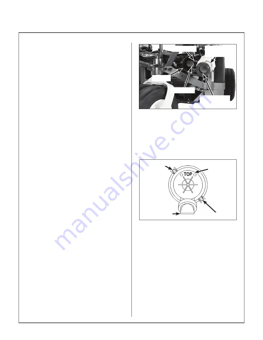
Radial Sealing


Surface

Primary


Filter Element

Canister

Safety Filter

Outlet Tube

Air Filter Element Replacement

10.  Install the cover with the word “TOP” properly 

oriented to the top of the canister.  Give the 

cover a slight twist as it reaches the canister to 

make sure the tab inside the cover goes into a 

slot, otherwise the cover will not fit properly.  

Make sure both the top and bottom cover 

latches are securing the cover in place.

Dust Ejection


Valve

Cover Latch

Cover Latch

Orient to Top


of Canister

Proper Orientation of Air Cleaner Cover

11.  Check the air intake hose for cuts, nicks, 

cracks, etc., and the hose clamps for tight-

ness.

12.  Reset the air filter restriction gauge (press 

button on the end of the indicator).

Engine Cooling System

Radiator Screen and Cooling Fins

To prevent the engine from overheating and pos-

sible engine damage, clean grass clippings, chaff, 

and dirt from the fine mesh radiator intake screen 

daily.

  In certain mowing conditions (dry grass, 

leaves, tree “cotton”, etc.), it may be necessary to 

check and clean the screen several times during 

use to prevent engine overheating.

Summary of Contents for D21d

Page 1: ...nd Save These Instructions For Safety Read All Safety and Operation Instructions Prior to Operating Machine Operator s Manual Safety Assembly Operating and Maintenance Instructions Beginning S N 17013...

Page 2: ...ry to the operator or others If anything in this manual is confusing or hard to understand please contact your local authorized dealer or call our service department at 970 221 5614 for clarification...

Page 3: ...and Function 30 Operating Controls 30 Engine Throttle 30 Forward Speed Control FSC 31 Steering Levers 31 Blade Clutch PTO 31 Parking Brake 31 Front Body Latch Release 33 Transmission Lockout Levers 33...

Page 4: ...Servicing 73 Engine Cooling System 73 Coolant Level 73 Alternator Belt Tension 74 Security of Air Filtration Components 74 Battery 74 Cleaning the Terminals 74 Charging the Battery 75 Tire Pressure 75...

Page 5: ...drive the main wheels HYDROSTATIC TRANSMISSION transmits and controls power from the ground drive belt to the main drive wheel LEFT HAND LH refers to the left hand side of the tractor when the operat...

Page 6: ...ant to find a local authorized servicing agent of the component man ufacturer Any unauthorized work done on these components during the warranty period may void the warranty If you have any difficulty...

Page 7: ...Air Cleaner Remote Mounted Donaldson RadialsealTM Walker P N 5090 1 Primary 5090 3 Safety Filter ELECTRICAL SYSTEM Battery 12 Volt 350 CCA Interstate SP 40 Charging System 40 Amp Automotive Alternator...

Page 8: ...Drive Oil Capacity fl oz L 24 0 71 Ground Travel Speed Forward MPH km h Reverse MPH km h 0 7 0 11 Infinitely Variable 0 5 0 8 Infinitely Variable BLADE DRIVE PTO Shaft Quick Disconnect Sliding Spline...

Page 9: ...ee Blade Paddle Wheel Blower Brake Band Brake Works in Combination with PTO Clutch Stops Blower within Five 5 Seconds of PTO Disengagement Max Blower RPM 4000 Hi Dump Option Max Lift Capacity lb kg 20...

Page 10: ...tor Only Outside Tire 39 99 Tractor with 48 Collection Deck DC48 1 49 25 125 Height in cm Tractor 50 127 Weight lb kg NC Tractor Only 787 357 GHS Tractor Only 959 435 NC Tractor with 48 Side Discharge...

Page 11: ...rass Handling System 10 0 Bushel Catcher Catcher Lift Dump Handle Fuel Tank and Cap Tilt Up Hook Tilt Up Deck Handle Deck Support Pins and Height Adjustment Hitch Pins Counterweight Spring and Protect...

Page 12: ...r Removable Grass Catcher Screen Not Visible Catcher Air Exhaust Catcher Door Handle Dump Flap Anti Scuff Roller Coolant Recovery Tank Tailwheel Fork and Wheels Radiator Screen Instrument Panel Guard...

Page 13: ...Gearbox Dipstick Precleaner Tube Air Filter Restriction Gauge LH Transmission Lockout Lever LH Hydrostatic Transmission Battery Neutral Safety Switch Negative Battery Cable Positive Battery Cable RH...

Page 14: ...mp Glow Plug s Alternator Fuel Return Line Fuel Gauge Fuel Tank Cap Fuel Pickup Line Thermostat Housing and Thermostat Water Temperature Gauge Sender Exhaust Manifold Oil Fill Cap Starter Motor Below...

Page 15: ...ed by Walker Manufacturing must take full responsibility for safety The Walker Rider Lawnmower has been designed with many safety features to protect the operator from personal harm or injury However...

Page 16: ...ls in the operating position 1 Forward Speed Control FSC out of NEUTRAL PARK 2 PTO Clutch ENGAGED or 3 Parking Brake DISENGAGED NOTE There is a 1 2 second time delay function on the seat switch to avo...

Page 17: ...n ignition interlock switch normally prevents starting of the machine if these controls are in the OPERATING position 7 Do not operate machine if the operator presence safety switch system is not work...

Page 18: ...me The door may slam shut with consider able force CAUTION Use leg muscles and firm footing when lift ing the catcher to dump avoid bending at the waist and using back muscles in order to prevent back...

Page 19: ...on the engine Unauthor ized maintenance operations or modifications to the engine may result in unsafe operating conditions 7 Altering the equipment or engine in any man ner which adversely affects it...

Page 20: ...to increase speed back to stop 3 Warning do not operate the machine without a deck or other implement attached 4 PTO Clutch Lever Move lever forward to disengage PTO clutch back to engage 5 Warning do...

Page 21: ...00 39 Warning stop engine and remove ignition key before adjusting deck cutting height Location Deck Carrier Frame Part Number 8600 15 Warning lock deck tilt up hinge before operating the machine 8600...

Page 22: ...r LH and RH Sides Part Number 8600 10 Caution Pinch point Keep all body parts clear when closing grass catcher door Location LH Gear Axle Part Number 5810 3 Location Oil Reservoir Part Number 5024 24...

Page 23: ...nual before operating the machine Warning wear eye and ear protection when operating the machine 2 Warning roll over hazard Do not operate on slopes greater than 15 degrees 3 Warning thrown object haz...

Page 24: ...mage to the case resulting in acid leakage and severe damage to the machine A hazard may be created by damage to critical working parts and safety systems CAUTION Important Battery Service Installatio...

Page 25: ...bolt and nut from each deck caster wheel fork 2 Fit a bearing cup on the outside of each wheel bearing and slide the wheel assembly into the wheel fork 3 Insert the 3 8 16 x 4 1 2 in bolt through the...

Page 26: ...r Wheel Installation Mount the two 2 tilt up roller wheels on the brack ets on the rear skirt of the deck housing using the P N 8490 axle bolt 3 8 in plain washer 3 8 in wave spring washer between bra...

Page 27: ...t PTO Coupler U Joint Quick Disconnect Ring Released Position Coupler Ring in Locked Position PTO Drive Shaft PTO Coupler U Joint Internal Balls Locked on Shaft Quick Disconnect Ring Locked Position I...

Page 28: ...e deck tilt up pivot joint unlocked Deck Lock Lever Engaged Deck Lock Levers Engaged 10 Raise the mower body and clip the counter weight springs to the receptacle on front of body as shown in the Inst...

Page 29: ...dure 2 Check the side to side level Rotate each blade sideways and measure the distance from blade tip to ground on each side If mea surements vary more than 1 8 in 3 mm add a washer shim under the de...

Page 30: ...the rear 1 4 in 6 mm to 3 8 in 10 mm higher than the front If either set of measurements are not within tolerance perform the Deck Leveling Procedure Deck Leveling Procedure 1 Position the mower on a...

Page 31: ...ica tions on page 3 F FILL FUEL TANK Fill the fuel tank with clean fresh fuel Clean diesel fuel is particularly important since con taminated fuel will damage the fuel injectors and injection pump NOT...

Page 32: ...leaving the seat with tractor moving forward or with the mower blades engaged F CHECK TIRE PRESSURE Deck Caster Wheel 20 PSI 137 kPa Drive 15 PSI 103 kPa Tailwheel 20 PSI 137 kPa If equipped with opti...

Page 33: ...tilt up position Do not move the tractor with the deck in the tilt up position F CHECK MOWER BLADE CONDITION SHARPNESS AND SECURITY OF MOUNT ING The blade mounting nuts on gear driven decks should be...

Page 34: ...tant for safe and efficient operation of the mower Engine Throttle The throttle control lever red knob is located on the left side of the seat and is used to control engine speed Moving the lever forw...

Page 35: ...ver stroke The levers are released to the FORWARD position for straight ahead ground travel NOTE Pushing forward on the steering levers will not cause any change in tractor motion there will be no ste...

Page 36: ...sition of the Steering Levers RIGHT WHEEL STEERING LEVER LEFT WHEEL STEERING LEVER Forward Position No Control Change Reverse Drive Wheel Motion Position Neutral Park Position Engaged Position Disenga...

Page 37: ...OUT position is used to enable moving the machine without the engine running e g for service Refer to Transmission Lockout on page 45 for operating instructions Lockout Levers Transmission Plunger Loc...

Page 38: ...ried out If you fail to do so your health may be affected and the risk of accident increased CAUTION Before the tractor is used the safety switch must be checked for proper function The operation of t...

Page 39: ...ing the height of the armrest pry out the round cap arrow of the cover and loosen the hexagon nut size 13 mm situated behind it Set the armrests in the desired position 5 steps and tighten the hexagon...

Page 40: ...ated on the instru ment panel Instrument Panel Warning Horn Light Switch Optional Hourmeter Circuit Breaker 10 Amp Headlights Fuel Pump Circuit Breaker 7 Amp Instrument Panel Safety Switches Fuel Valv...

Page 41: ...em failure The cause of the failure should be deter mined and corrected Water Temperature Gauge The water temperature gauge monitors engine cooling system temperature If engine coolant temperature exc...

Page 42: ...d cranking can damage the starter motor and shorten battery life Release the key when the engine starts and it will return to the ON RUN position To stop the engine rotate the key coun terclockwise to...

Page 43: ...kshaft Drive Belt Release 2 Turn and hold the ignition key in the PRE HEAT position to preheat the engine glow plugs For temperatures below 35 F 2 C the time required is approximately 10 seconds For t...

Page 44: ...not nec essary to hold the FSC lever in position since a friction lock maintains the selected lever position and forward travel speed CAUTION An operator presence switch seat switch will cause the en...

Page 45: ...emember for an emergency stop or in case of loss of control machine movement can always be stopped quickly by pulling the Forward Speed Control into the NEU TRAL PARK po sition Pull Steering Levers wi...

Page 46: ...HE BLADE DRIVE 1 Set the engine throttle at about 1 3 speed Do not attempt to engage the blade clutch at high engine speeds This will drastically short en drive belt life Use only moderate engine spee...

Page 47: ...from the ignition switch when leaving the mower unattended This will prevent children and inexperienced op erators from starting the engine 5 Engage the parking brake IMPORTANT The hydrostatic transm...

Page 48: ...e adjusting cutting height or servicing move the Forward Speed Control FSC into the NEUTRAL PARK position engage the parking brake and disengage the blade clutch PTO Tractor should not be moving while...

Page 49: ...Depressed Cam in LOCKOUT Position Lockout Lever Freewheel Position 4 After moving the mower release the locking cam placing the lever DOWN in the normal OPERATING position Make sure the trans mission...

Page 50: ...n the grass Avoid damage to the grass by slipping and skid ding of the drive tires Use smooth control move ments of the steering levers since the hydrostatic transmissions are power boosted controls a...

Page 51: ...lt up position since both the roller wheels on the back of the deck and the GHS discharge chute may be damaged by moving the tractor The tilt up configuration should only be used when the tractor is p...

Page 52: ...ection Mower Deck Grass Catcher Catcher Air Exhaust Powerfil Drive Motor Actuator Rod Full Signal Horn Grass Pak Vane Switch Exhaust Screen Removable Catcher Door Spring Not Visible Powerfil Delivery...

Page 53: ...ves particularly when the leaves are piled in a thick layer To make this ad justment the hitch pins in the two 2 front deck support pins are repositioned 2 to 3 notches higher while leaving the rear p...

Page 54: ...Nut Torque 60 lb ft 81 N m Blade Rotation for Standard Rotation GHS Mower Deck Bottom View FORWARD Rear Discharge Chute Blades Must Operate at Right Angles 90 Degrees Mounting Nut Torque 60 lb ft 81 N...

Page 55: ...ay be checked by turning the ignition switch to the ON RUN position and moving the blade clutch to the ENGAGED position The spout should oscillate approximately 35 cycles per minute NOTE If the grass...

Page 56: ...ilgate dumps into a disposal area or dumps into the optional dump bag The dump bag is a reusable nylon fabric bag designed to conveniently move grass clippings from the catcher to a remote disposal ar...

Page 57: ...ith the one hand while continuing to hold up on the bag strap with the other hand Refer to photos for posi tioning the bag and dumping Catcher Lift Dump Handle Dumping Catcher into Dump Bag 5 Lower th...

Page 58: ...raising the catcher with the power dump jiggle the steering levers and make the tractor bounce a little to unstick the grass and make it slide out of the catcher NOTE With the power dump mechanism in...

Page 59: ...in the NEUTRAL PARK Position and the parking brake engaged and by standers stay clear when the Hi Dump is operating To avoid tipping over the ma chine should be parked on LEVELGROUND when raising dum...

Page 60: ...onents 1 2 Catcher Door Grass Catcher Cable Guide Door Arm Actuator Lower Arm Dog Leg Assembly Actuator Mount Assembly Gas Spring Cable Assembly Rubber Bumper Lift Channel Power Dump Ram Actuator Fork...

Page 61: ...ble Grass Catcher Cable Assembly Hydraulic Reservoir Power Unit Lift Toggle Switch Safety Lockout Arm Lift Cylinder Hydraulic Valve Block Lower Arm Door Arm Actuator Dump Cylinder Catcher Pivot Arm Ca...

Page 62: ...ing Fins x 73 Change Engine Oil Filter x 60 Check Radiator Hoses and Clamps x 77 Change Hydrostatic Transmission Oil and Filter x 64 Replace Fuel Filters x 86 Check Fuel Lines and Clamps x 76 Replace...

Page 63: ...the radiator and overflow tank Operate the engine at full speed when mowing This allows the engine to produce full horsepower and move more cooling air through the radiator Air Cleaner System Use onl...

Page 64: ...er stopping the engine IMPORTANT NEVER check or add oil with the engine running 2 Before removing the dipstick clean the area around the dipstick to keep any dirt or debris out of the engine 3 Remove...

Page 65: ...ion al 1 2 to 3 4 turn 8 Reinstall the drain plug Make sure it is tight ened to 10 lb ft 14 N m 9 Fill the crankcase with new clean oil Use only crankcase lubricants recommended by the engine manufact...

Page 66: ...rallel to cover plate NOTE In case the gearboxes are completely drained of oil approximately 5 fl oz 15 cl of oil per gearbox is required to refill the gear drive assembly NOTE Since the gearboxes are...

Page 67: ...ed and rebuilt PTO Gearbox Dipstick Jackshaft Vent Plug Dipstick Location Tractor PTO Gearbox Changing Gearbox Oil The tractor PTO gearbox is oil filled No scheduled oil change is required However cha...

Page 68: ...d oil The only Walker approved oil for the transmis sions is Mobil SHCTM 630 oil Walker P N 6450 20 Thoroughly clean around the res ervoir fill cap before removing the cap Add oil until it is at the m...

Page 69: ...through the fill opening for the air foam to dissipate Add additional oil to reach the cold fill line about half way up the sight gauge window if necessary Fill Plug Reservoir Fill Cap Fill Plug Fill...

Page 70: ...26 ClutchActuator Push Rod Grease 2 Ident Lubrication No No Location Type Places 27 Brake Band Pivot Pin Clevis Oil 1 28 Belt Tightener Pivot Grease 1 PTO Clutch 29 Throttle Control Cable Ends Oil 2 3...

Page 71: ...ance Instructions Lubrication 67 Chassis and Deck Lubrication Points DC42 Shown 1 1 2 2 11 11 12 19 19 14 14 16 15 21 23 18 20 20 24 22 29 27 30 31 29 38 32 32 33 34 37 37 36 7 5 5 13 13 4 4 4 4 17 25...

Page 72: ...parates dust from the air giving the initial stage of air clean ing Dust particles are exhausted through a single small vent in the side of the hous ing Since no dust is trapped the precleaner oper at...

Page 73: ...Ser vice the air cleaner as follows 1 Release the top and bottom cover latches and remove the air cleaner cover Wash the cover and dust ejection valve Check that these com ponents are in good conditio...

Page 74: ...s completely in place before installing the cover IMPORTANT DO NOT use the cover latch es to force the filter into the canister the cover should fit on with no extra force NOTE DO NOT use petroleum ba...

Page 75: ...and flush the cooling system thor oughly before adding fresh coolant Use a pre mixed 50 50 solution of antifreeze eth ylene glycol and distilled water to refill the cooling system IMPORTANT The soluti...

Page 76: ...Before attempting to wash the blower stop the engine remove the ignition key and electrical plug on the fuel shut off solenoid Wear goggles or face shield 1 Remove the GHS blower drive belt tension b...

Page 77: ...ect the cooling fans Replace the fan s if blades are missing or damaged Cooling Fins Cooling Fan Hydrostatic Transmission Cooling Fins CHECKING SERVICING DANGER To prevent accidental starting of the e...

Page 78: ...3 Check to make sure the air filter restriction gauge is in place and hose connections are secure Battery The battery comes sealed and is maintenance free so the electrolyte level will not need to be...

Page 79: ...es NOTE Keep blades sharp cutting with dull blades not only yields a poor mowing job but slows the cutting speed of the mower and causes extra wear on the engine and blade drive by pulling hard 1 Stop...

Page 80: ...shown in Clog ging Checklist on page 50 for correct blade rotation Drive Belts Raise the body and inspect the condition of the five 5 belts 4 belts on SD models every 25 hours of operation engine PTO...

Page 81: ...ctor nozzle or any part of the fuel injection system Transmission Control Setting On a yearly interval or when an out of adjustment condition is observed check the transmission control for proper func...

Page 82: ...ake is disengaged and the Forward Speed Control FSC or PTO is engaged Without an operator in the seat the engine starts and continues to run with the Forward Speed Control FSC and or PTO engaged or th...

Page 83: ...AN result in product malfunction and possible injury to the operator and or others Drive Belts There are five 5 individual belts on GHS mod els or four 4 belts on SD models Jackshaft Drive Belt Engine...

Page 84: ...f the engine and PTO pulleys one groove at a time until the belt is com pletely removed 2 Install the PTO drive belt by reversing the removal procedure 3 Refer to Blade Clutch PTO on page 91 to check...

Page 85: ...rm up and away from the belt c Roll the belt off the jackshaft pulley and remove Jackshaft Drive Belt Disengaged Jackshaft Drive Belt Engaged Jackshaft Pulley Jackshaft Drive Belt Idler Arm Release Sp...

Page 86: ...ightener arm Roll the belt off the blower pulley GHS Blower Drive Belt Assembly Disengaged GHS Blower Drive Belt Assembly Engaged Depress Idler Pulley Down to Relax Belt GHS Blower Drive Belt Blower D...

Page 87: ...belt b Slide belt off pulleys then release the idler Hydrostatic Ground Drive Belt Assembly Disengaged Hydrostatic Ground Drive Belt Assembly Engaged Transmission Drive Pulley Spring Jackshaft Belt T...

Page 88: ...hown to relax and remove belt Engine Alternator Belt Loose Engine Alternator Belt Tight Alternator Bracket Crankshaft Pulley Engine Alternator Belt Alternator Tensioner Bolt Water Pump Pulley Alternat...

Page 89: ...g Rotate Clevis and Belt Tensioner Stop Bolt Rotate Belt Tensioner Arm Remove Belt Tension 2 To install the deck drive belt a Install and route the belt as shown on the belt routing decal located on t...

Page 90: ...60 5 Open the fuel filter cock Blade Overload Shear Bolts NOTE Blade shear bolts are not used on belt driven decks On gear driven decks each cutting blade is keyed to the blade hub by two 2 shear bolt...

Page 91: ...perated over sandy soil and if blades are allowed to wear a slot may be worn into the wing tip of blade Eventually a piece of the blade may break off creating a serious potential for injury or damage...

Page 92: ...levers should be adjusted to sit evenly using the following procedure 1 Examine the steering levers to make sure they are parallel front to back in relation to one another If they are not equal adjust...

Page 93: ...ins to move backward then make two addi tional turns Next reverse and turn the control rod clockwise CW until the steering lever stops moving forward and then make one additional turn Tighten the jam...

Page 94: ...adjustment should be made for one wheel stationary and the other moving forward slightly 6 Check the neutral safety switch for closure and function with the FSC in neutral the en gine will not start w...

Page 95: ...y linkage to the clutch idler pulley mechanism The brake is designed to stop the blades within five 5 seconds after disengaging the clutch Use the following procedure to check and adjust clutch diseng...

Page 96: ...n the steering levers are moved The friction should not be so heavy as to make moving the FSC difficult too much friction The procedure for checking and adjusting the FSC friction lock is as follows F...

Page 97: ...ted by loosening the locknut at the pivot point and the locknut holding the handle in position in the adjustment slide Adjust handles into most comfortable position and tighten both locknuts Locknut P...

Page 98: ...h with the engine running Projectiles CAN be thrown out of the grass delivery spout and CAN cause serious injury to bystanders or property damage 2 Measure from the exhaust screen top of catcher to th...

Page 99: ...IS WARRANTY DOES NOT COVER A This warranty does not cover defects caused by depreciation or damage caused by normal wear accidents improper maintenance improper use or abuse of the product alterations...

Page 100: ...WALKERMFG CO 5925E HARMONYROAD FORTCOLLINS CO80528 970 221 5614 FORM NO 121922 PRINTED IN USA www walker com 2022 WALKER MFG CO...

Reviews: