48
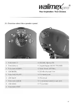
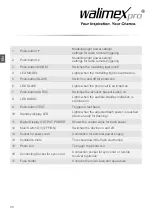
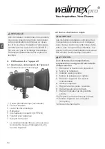
1
Push-button
Modelling light power setting/
settings for radio remote triggering
2
Push-button
Modelling light power setting/
settings for radio remote triggering
3
Push-button MODEL
Switches the modelling light on/off
4
LED MODEL
Lights when the modelling light is switched on.
5
Push-button SLAVE
Switch on and off for photo cell
6
LED SLAVE
Lights when the photo cell is switched on.
7
Push-button AUDIO
Switches the acoustic beeper button on
8
LED AUDIO
Lights when the audible standby indication is
switched on.
9
Push-button TEST
Triggers a test flash
10
Standby display LED
Lights when the adjusted flash power is reached
(device ready for flashing)
11
Digital Display OUTPUT POWER
Shows the control value for flash power
12
Main Switch O/I (OFF/ON)
Switches the device on and off
13
Socket for power cord
Connection for external power supply
14
Ventilation slots
This cools down the flash electronics.
15
Photo cell
To trigger the photo cell
16
Connecting Socket for sync cord
Connection socket for sync cord or remote
receiver (optional)
17
Fuse holder
Contains the micro-fuse and spare fuse
EN

