background image

19 

Cleaning and Maintenance


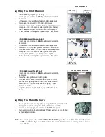
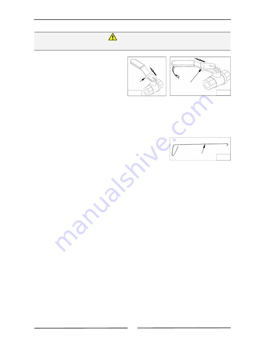
Opening the Drain Valve 

a.  Lift locking slide on valve handle  

(Fig 11) to release valve. 

b.  While holding locking slide in  

withdrawn position, rotate handle 

anticlockwise (Fig 12) to open valve. 

c.  When valve is closed, locking slide will 

drop down over locking valve to 

prevent accidental opening of valve as 

shown in Fig.11. 


4. 

Do not empty total fryer contents into one large container, as this will be dangerous and may be 

difficult, when lifted up, to pour hot oil back into tank. 

5. 

Slip a muslin or other suitable filter bag over the end of the drain valve.  Crumbs will be caught in 

the bag but frying medium will strain freely through into receptacle. 

6. 

Open drain valve slowly to minimise splashing, and take care not to overfill container. 

7. 

If necessary, use the drain stick (see Fig 13) to dislodge any  

blockages in the drain. 

8. 

When tank has been drained, use a ladle or small pan with a 

handle and dip into hot frying medium from container and pour 

around sides and bottom of tank to wash out crumbs and 
particles adhering to tank. 

9. 

Continue to dip and pour until all crumbs are washed down and into filter bag. 

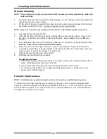
10.  Open drain valve fully and check for any particles or crumb residue lodged in valve.  Clean out valve 

with a stiff nylon brush.  Do not use a wire brush as this can damage valve seating and will  
eventually lead to leakage.  If obstruction cannot be removed with a brush, use a wooden probe to 

dislodge obstruction. 

11.  Wipe all exterior panels with a cloth dampened with detergent and rinse off any residue with clean 

warm water. 

12.  Clean Control Panel with a damp cloth lightly moistened with a solution of water and a commercial 

quality foodservice approved detergent. 

13.  Once the daily cleaning operation is completed, close drain valve and pour frying medium back into 

tank. 


H

OT


OIL


WILL


BURN

 - D

O

 N

OT


RUSH


THIS


JOB

Warning 

Fig 12 

Fig 11 

Locking Slide 

Locking 

Slide 

Fig 13 

Drain Stick 

Summary of Contents for FN8120GE

Page 1: ...O p e r a t i o n M a n u a l FN8120GE FN8226GE FN8130GE Fast Fri Gas Fryer E l e c t ro n i c a l l y C o n t ro l l e d Date Purchased Serial Number Dealer Service Provider 228638 16 For use in GB I...

Page 2: ...es tel 1800 337 963 Customer Service tel 1800 335 315 fax 1800 350 281 CANADA Serve Canada Web www servecanada com E Mail info servecanada com Sales tel 800 551 8795 Toll Free Service tel 800 263 1455...

Page 3: ...itting Rear Rollers Electrical Connection Gas Connection Commissioning Operation 12 Operation Guide Description of Controls Filling the Tank s Controller Basic Programming Mode Entering the Controller...

Page 4: ...27 Timing Mode Temperature Offset Temperature Display Mode Programming the Melt Cycle Setting the Temperature Units System Programmable Default Settings Gas Conversion and Specifications 30 Conversion...

Page 5: ...ppliance must NOT be left on unattended It is recommended that a regular inspection is made by a competent service person to ensure correct and safe operation of your appliance is maintained DO NOT st...

Page 6: ...ac 1P N E 50Hz 0 5A Electrical Connection The power cord comes fitted with Australia NZ models 10A 3 pin plug United Kingdom models 13A 3 pin fused plug Natural Gas LP Gas Propane Input Rating 90MJ hr...

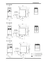
Page 7: ...5 Dimensions FN L 8130GE 3 3 2 1 2 1 3 2 1 FN L 8226GE 3 2 1 3 3 2 1 2 1 FN L 8120GE 3 2 1 3 3 2 1 2 1 1 Primary Gas Entry Point 2 Optional Gas Entry Point 3 Electrical Entry Point...

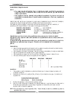
Page 8: ...ected e g paint sealed by manufacturer are only to be adjusted by an authorised service agent They are not to be adjusted by the installation person Unpacking Remove all packaging and transit protecti...

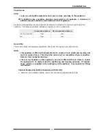
Page 9: ...y attached NOTE This appliance is fitted with adjustable feet to enable it to be positioned securely and level on uneven floors This should be carried out on completion of gas connection Refer to Gas...

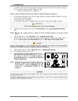
Page 10: ...rear leg housings 3 Fit rear roller to rear leg housing and align screw hole in side of rear leg housing with threaded hole in rear roller 4 Secure the rear roller to the leg support with bolt suppli...

Page 11: ...meets the following requirements NOTE ALL GAS FITTING MUST ONLY BE CARRIED OUT BY A QUALIFIED SERVICE PERSON 1 It is essential that the gas supply is correct for the appliance being installed and tha...

Page 12: ...and Specifications section Pilot Burner Flame Adjustment 9 Light the Main Burners Refer to Operation section Lighting Main Burners 10 Verify Supply Pressure is still correct 11 Check Main Burner oper...

Page 13: ...the calibration of the thermostat If a discrepancy is found thermostat calibration should be referred to the supplier d Ensure each operator has been instructed in areas of correct lighting operation...

Page 14: ...r should not be adjusted by the user operator Caution O Fig 4 Piezo Igniter Gas Control Valve OFF Position PILOT Burner HIGH Flame Flame Failure Button Single Tank Models Only NOTE Only one temperatur...

Page 15: ...to access the parameter setting required a If LoC is displayed control panel is locked which will prevent any accidental change to the operating mode b To access parameters whilst LoC is displayed on...

Page 16: ...ol panel display Refer to Controller Advanced Programming Mode section to change Heating will automatically cycle at a lower temperature to gently melt the shortening THE OPERATOR MUST TAKE GREAT CARE...

Page 17: ...Items 1 to 4 above FN8226GE Fryer Twin Tank 1 Rotate gas control knob to Pilot position and hold knob depressed 2 Press the piezo igniter until pilot ignites 3 Hold gas control knob depressed for app...

Page 18: ...ntroller Refer to Controller Advanced Programming Mode section for controller advanced programming If Melt Cycle is turned ON If Melt Cycle is turned OFF If t 0 selected in Advanced Program Settings d...

Page 19: ...ess and rotate gas control valve fully clockwise to the Off position b The Pilot burners will extinguish IMPORTANT Should any abnormal operation like ignition problems abnormal burner flame burner con...

Page 20: ...ining and Daily Cleaning 1 At end of each day or at end of each shift if frying schedule is heavy frying medium should be drained and filtered into a receptacle 2 Always filter fryer when cool zone un...

Page 21: ...k has been drained use a ladle or small pan with a handle and dip into hot frying medium from container and pour around sides and bottom of tank to wash out crumbs and particles adhering to tank 9 Con...

Page 22: ...yer and rinse thoroughly with water Use a 1 part vinegar to 15 parts water solution to rinse tank and neutralise any cleaner residue If this proves unsuitable for cleaner being used use a weaker solut...

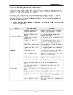
Page 23: ...fried Continued overheating of oil Check thermostat setting Turn down heat to around 140 C Standby when use is quiet Overloading Maintain 1 8 ratio of food to frying medium Gumming Heating frying medi...

Page 24: ...ficient turnover of oil Maintain a minimum quantity of oil in fryer for more rapid turnover or increase quantity of food fried in fryer Replace with fresh oil every 3 to 5 days Continual frying with e...

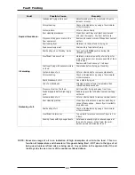
Page 25: ...ure Call for service Faulty thermocouple Call for service Faulty overtemp Call for service Faulty gas control valve Call for service Pilot Burner goes Out during operation Low fluctuating gas pressure...

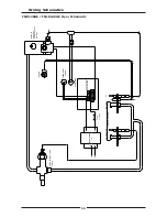
Page 26: ...NL8120GE Fryer Schematic T C FLAME FAILURE VALVE SIT M1 A MAIN GAS CONTROL SIT NOVA 820mV 24V 50Hz THERMOSTAT OVER TEMP IGNITION L H PILOT T C R H PILOT CROSS LIGHTING TRANSFORMER 24v P N FUSE 2 0 Amp...

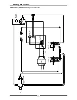
Page 27: ...er Schematic TH MAIN GAS CONTROL SIT NOVA 820mV 24v 50Hz MAIN GAS CONTROL SIT NOVA 820mV 24v 50Hz PILOT PILOT T C TC IGNITION OVER TEMPS THERMOSTAT IGNITION FAST DIGITAL CONTROLLER FAST DIGITAL CONTRO...

Page 28: ...E FNL8130GE Fryer Schematic T C FLAME FAILURE VALVE SIT M1 A MAIN GAS CONTROL SIT NOVA 820mV 24V 50Hz THERMOSTAT OVER TEMP IGNITION L H PILOT T C R H PILOT TRANSFORMER 24v P N FUSE 2 0 Amp FAST DIGITA...

Page 29: ...cked Unlock the control panel refer to Controller Basic Programming Mode Entering the Controller Basic Settings and repeat from Item 2 above Timing Mode 1 One of the following options will display Str...

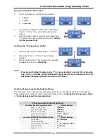
Page 30: ...perature offset option press either Timer 1 or Timer 3 key to change selection 3 Press Program Key P to confirm the change and the display will step on to Temperature Display parameter Temperature Dis...

Page 31: ...oximately 3 seconds Or not pressing any keys for 2 minutes during Advanced Programming Mode the appliance will exit Advanced Programming Mode and return to Idle Mode System Programmable Default Settin...

Page 32: ...his section Main Burners 1 Remove main burner injectors and replace with correct size injectors as shown in Gas Specifications table Pilot Burners 1 Remove the following Gas supply tube to the pilot b...

Page 33: ...ermocouple and thermopile is correct and main burner pilot flame ignites main burners satisfactorily b Adjust pilot flame size by adjusting Pilot Burner Adjusting Screw Pilot burner flame should be ap...

Page 34: ...h Flame setting Refer to Gas Conversion and Specification Section for further details Natural Gas G20 LP Gas Propane G31 Main Burner Injectors 3 10mm 1 90mm Pilot Burner Injectors Non CE 0 62 0 35 CE...

Page 35: ...17 Gas Control 24V 229158 Gas Valve Cable Plug 24V FN8120GE FN8226GE Only 229159 Gas Valve Cable Plug 24V FN8130GE Only 019237 Flame Failure Valve FN8120GE FN8130GE Only 018095 Piezo H T Lead 020119 P...

Page 36: ...228577 Basket Tray FN8226GE 228578 Basket Tray FN8130GE 228419 Lid FN8120GE FN8226GE 228575 Lid FN8130GE 229674 Rear Roller Assy 227850 Leg Adjustable 150mm Flush Stud Gas Conversion Kits Accessories...

Page 37: ......
Reviews: