WAGO-TO-PASS® 761
Parameterizing
85
761-217 Telecontrol Module Compact, 8 AI, Web, MODBUS485
Manual
Version 1.0.0
7.10
Data Logger
Select the
TO-PASS
®
telecontrol module from the project tree using the identifier.
Select the entry
Data Logger
under the option
Special Functions
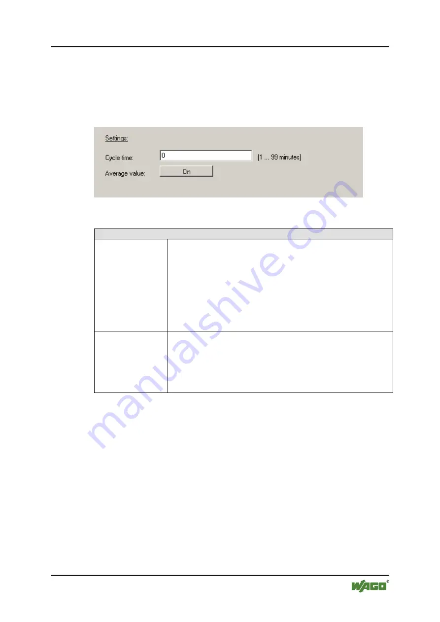
. The input field
for the cycle time and a button for calculating the average value are located on the
right side.
Figure 39: Configuring the data logger
Table 41: Configuring the data logger
Settings
Cycle time
In this field enter the cycle time in minutes at which the
process image is to be saved.
The process image is specific to devices and firmware used
and is described in the Section "Operation – Data Logger
(DSP)".
The data logger is a cyclic buffer; i.e., when the buffer is full,
the oldest process images are overwritten (F.I.F.O). The size
of the data logger depends on the device used and is specified
in the technical data sheet.
Average value
Press the
[On]
button to switch average value calculation on
or off.
If average value calculation is on, the analog input values
read at a sampling rate of 10 ms are added within a cycle
time. The total is than divided by the number of values read
in the cycle time and saved.


