Serie 750, 753
Assembly and Disassembly
System manual | Version: 3.0.2
47
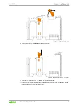
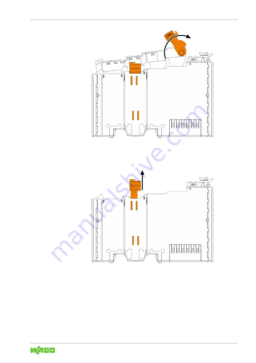
Figure 27: Pulling the Locking Latch
2. Pull up the orange release tab on the I/O module.
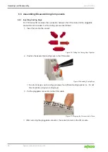
Figure 28: Detaching the 753 Series I/O Module
3. Pull the I/O module out of the assembly by the release tab.
ð
When the I/O module is pulled out of the assembly, the electrical connections of the
data and power contacts are separated.


