Serie 750, 753
Planning
36
System manual | Version: 3.0.2
U
S
U
F1
FE
1
2
3
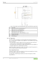
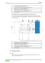
Figure 17: Power Supply Concept for Marine Applications – Class A and B with FE Power Jumper Contact
1
Head station
2
Filter module, 24 VDC, HI GF (750-626/020-002) or
filter module, 24 VDC, HI (750-626/020-000) or
filter module, 24 VDC, HI / T (750-626/025-001)
3
Bus supply module, 24 VDC (750-602) or
bus supply module, 24 VDC, with fuse (750-601) or
bus supply module, 24 VDC, with fuse and diagnostics (750-610)
U
S
System supply (24 VDC)
U
F1
Field supply 1 (24 VDC)
FE
Functional ground
4.5.2 Ex i Applications
Some I/O modules are intended to be connected with devices located in hazardous ar-
eas. To ensure safety and reliability in these applications, several additional requirements
must be considered:
• The node structure meets the additional requirements specified below for the power
supply as well as the requirements for air and creepage distances.
• The operator obtains a prototype test certificate that confirms the correct installation of
the system and store it in a control cabinet or housing.
Observe the detailed requirements as stated in the original wording of the respective cer-
tificate (Installation Regulations Specified by Approvals).
Power Supply Requirements
Only Ex i bus supply modules are permitted to be used for power supply to any node sec-
tions containing I/O modules for Ex i applications.
The following Ex i potential supply modules may be used for this purpose: 750-606,
750-625/000-001.


