background image

5

PC 1030

Mortar hose

Danger of injury through leaking high-

pressure hose. Wear and tear and links as 

well as usage that is not appropriate to the 

purpose of the device can cause leakages 

to form in the mortar hose. Liquid can be 

injected into the skin through a leakage. 

Mortar hoses must be checked thoroughly before they are 

used.

Replace any damaged mortar hose immediately. 

Never repair defective mortar hoses yourself! 

Avoid sharp bends and folds: the smallest bending radius is 

about 80 cm.

Do not drive over the mortar hose. Protect against sharp ob-

jects and edges.

Never pull on the mortar hose to move the device.

Do not twist the mortar hose.

Lay the mortar hose in such a way as to ensure that it cannot 

be tripped over.

Only use WAGNER original-mortar hoses in 

order to ensure functionality, safety and du-

rability.

The risk of damage rises with the age of the 

mortar hose.

Wagner recommends replacing mortar hoses 

after 6 years.

GB

SAFETY REGULATIONS

Summary of Contents for PLASTCOAT 1030

Page 1: ...Service manual with electrical repair instructions for electrically instructed persons of the J Wagner GmbH PC 1030 2369648 B 08 2021...

Page 2: ...following points are to be observed in accordance with the operating manual before every start up 1 Observe the permissible pressures 2 Check all the connecting parts for leaks 3 Instructions for regu...

Page 3: ...1 5 Five safety rules_______________________________ 20 1 6 Categorisation of protection classes______________ 21 1 7 Explanation of electric variables and components___ 22 1 8 Explanation of electric...

Page 4: ...ns of the German employer s liability insurance association Beruf sgenossenschaft Rules for the use of breathing masks BGR 190 and Processing coating materials BGV D25 Connection to the mains network...

Page 5: ...Never repair defective mortar hoses yourself Avoid sharp bends and folds the smallest bending radius is about 80 cm Do not drive over the mortar hose Protect against sharp ob jects and edges Never pul...

Page 6: ...ating pressure 40 bar Max granular size K6 mm Dimensions L x W x H 1150 x 550 x 620 mm Container capacity 50 l Weight PlastCoat 1030 60 kg Weight Spray lance 2 1 kg Max tyre pressure 2 5 bar Degree of...

Page 7: ...ied out by the person who controls the machine Never operate mortar spraying machine with an exposed rotor Do not reach into the rotor when it is mov ing Risk of crushing Caution if you have long hair...

Page 8: ...e the outlet unit 4 Set delivery volume controller 2 to 1 or 2 Connect mains plug to mains power supply Move the selector switch 1 to position F As soon as the stator 5 is released from the rotor 6 se...

Page 9: ...9 PC 1030 GB...

Page 10: ...ber seal flange 13 2357594 Receptacle ITEM ORDER NO DESIGNATION 14 348316 Rotor 15 348324 Screw 2 16 2360651 Feeder shaft 17 2360706 Rubber seal motor 18 9921501 Spring washer 4 19 9900313 Cylinder he...

Page 11: ...11 PC 1030 1 2 3 4 5 6 7 8 9 10 11 12 13 14 15 16 17 18 19 20 21 22 23 24 25 5 Nm Explanation xNm indicates torque 25 5Nm 25 5Nm GB SPARE PARTS ILLUSTRATION...

Page 12: ...2 3 4 5 6 ITEM ORDER NO DESIGNATION 1 3142039 Ring nut M12 2 3069013 Square head plug 3 2367604 Guide pulley 4 348349 Wheel 5 9994902 Wheel cap 6 2309787 Protective cap 8 1 SPARE PARTS LIST FRAME SPAR...

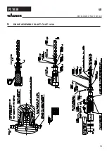
Page 13: ...13 PC 1030 9 DRIVE ASSEMBLY PLAST COAT 1030 GB DRIVE ASSEMBLY PLAST COAT 1030...

Page 14: ...Control knob for potentiometer 4 2315416 2308475 Switch 6 2313 743 Emergency stop switch 7 2313 481 Signal lamp green ITEM ORDER NO DESIGNATION 8 2313 482 Signal lamp red 9 2316 781 Adhesive label fro...

Page 15: ...15 PC 1030 GB...

Page 16: ...22 488 O ring 25 x 2 5 7 2323 764 Housing component left 8 2319 220 Lever 9 2322 363 Magnet 10 2319 228 Turn restrictor 11 9999 360 Retaining ring 12 2336 552 O ring 30x 2 8 2 pcs 13 2322 179 Slide bu...

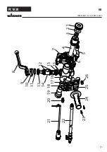
Page 17: ...17 PC 1030 GB SPARE PARTS LIST OF SPRAY LANCE 1 2 3 4 5 6 7 8 9 10 11 12 13 13 14 15 16 17 18 19 20 21 22 23 24 25 26...

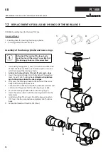
Page 18: ...cylinder 5 and all seals and o rings 3 Insert the closing cylinder 5 with the help of the guiding tools 1 and 2 into the lance body Attention Avoid dam age to the o rings due to the sharp edges 4 Full...

Page 19: ...nd indicate potential hazards and special features The work instructions must include safe and correct replace ment of a connecting cable for example 1 2 SKILLED ELECTRICIAN FOR DEFINED TASKS In order...

Page 20: ...ive parts All live cables must be disconnected at all poles at the place of work before starting work This can be done by means of main switches expert removal of fuses disconnection of plug connector...

Page 21: ...against electric shock in addition to the basic insulation Connection to the protective conductor system is not possible Appliances with this protection class are not permitted in Germany and Austria...

Page 22: ...aohms Designation Explanation L1 External conductor L2 External conductor L3 External conductor N Neutral conductor PE Protective conductor 3 Threephase AC voltage 1 8 EXPLANATION OF ELECTRICAL TERMS...

Page 23: ...ductor A PEN conductor is an earthed conductor which performs the function of protective conductor and neutral conductor simulta neously Active part of an electrical system An active part is a live pa...

Page 24: ...e wires then the wire is defective 7 The defective component must be made inoperative in order to prevent further use 2 2 FUNCTIONAL TEST OF THE CAPACITOR 1 Ensure safe isolation from the supply befor...

Page 25: ...strument should be used to check the electrical functionality If a multimeter is used it should be set to V or VAC 5 Now check the voltage present between L1 and N If this is 230 V AC then the voltage...

Page 26: ...be disconnected first of all Note down the connection plan 4 Measure all cables to the housing if a continuity is found then the motor has an earth fault and is defective 5 Measurement of the individu...

Page 27: ...asurement in accordance with BGV A3 must be carried out in order to ensure electrical safety and functionality See chapter 1 4 3 3 REPLACING THE CAPACITOR 1 Ensure safe isolation from the supply befor...

Page 28: ...h 4 The motor protecting switch can now be removed 5 Now install the new motor protecting switch and restore the electrical connection 6 After completing the repair a measurement in accordance with BG...

Page 29: ...r noting the exact pin assignment 3 Now replace the motor 4 Observe the pin assignment noted in point 2 when connecting the individual wires Also ensure secure contact when con necting the wires 5 Aft...

Page 30: ...LUG 230V 50 Hz GREEN YELLOW BLUE BROWN W U V GND MOTOR PLUG C 16 3 GND BLUE GREEN YELLOW BLACK H1 YELLOW H2 GREEN H3 BLUE 5V RED MOTOR 4 MACHINE SPECIFIC DOCUMENTS 4 1 Connection diagram PC 1030 CONNE...

Page 31: ...Tel Fax 0341 210100 centralino wagner_it_va wagner group com CH Wagner International AG Industriestrasse 22 9450 Altst tten Schweiz Tel 41 71 7 57 22 11 Telefax 41 71 7 57 22 22 wagner wagner group c...

Reviews: