26
PC 1030
GB
ELECTROTECHNICAL REPAIR INSTRUCTIONS: BASIC PRINCIPLES
2.6
FUNCTIONAL TEST OF THE THREEPHASE MOTOR
1. Ensure safe isolation from the supply before commencing work.
2. A multimeter should be used for testing; this must be set to ohm (Ω) and tested.
3. In order to obtain a reliable and meaningful measurement, all cables of the motor must be disconnected fi rst of all. Note
down the connection plan.
4. In order to determine an interwinding fault, the Y/Δ jumpers must be removed. Note down the connection plan.
5. Measure all motor cables to the housing; if a continuity is found, then the motor has an earth fault and is defective.
6. Measure all three windings individually; they must present the same resistance. If a deviation of ≥ 2.0% is found, the motor
has an interwinding fault and is defective.
7. If the motor is equipped with a thermal link, this must be tested for continuity. If no continuity is present or a resistance of ≥
5Ω is present, the motor is defective.
2.7
FUNCTIONAL TEST OF AC MOTOR
1. Ensure safe isolation from the supply before commencing work.
2. A multimeter should be used for testing; this must be set to ohm (Ω) and tested.
3. In order to obtain a reliable and meaningful measurement, all cables of the motor must be disconnected fi rst of all. Note
down the connection plan.
4. Measure all cables to the housing; if a continuity is found, then the motor has an earth fault and is defective.
5. Measurement of the individual windings is not possible, as they are internally bridged.
6. If the motor is equipped with a thermal link, this must be tested for continuity. If no continuity is present or if a high resi-
stance is present, the motor is defective.
3
REPAIR WORK INSTRUCTION
3.1
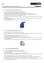
REPLACING A CORD SET
1. Ensure safe isolation from the supply before commencing work.
2. Remove the old cable, noting the contact confi guration.
3. Strip new cord set to desired length, taking care not to damage the insulation of the wires.
4. Shorten conductors N (blue) and L1 (brown) by 1.5 cm, to ensure that when there is a tensile load on the cable, the protective
conductor (yellow/green) is disconnected from the machine last.
5. Press on the wire end ferrules, to ensure secure contact.
6. Install strain relief in order to prevent the connecting cable from being pulled out. Make sure that the strain relief is not ex-
cessively tightened, which could cause the cable to shear off .
7. Ensure secure contact when connecting the individual wires.
8. After completing the repair a measurement in accordance with BGV A3 must be carried out, in order to ensure electrical
safety and functionality.
9. The defective component must be made inoperative in order to prevent further use.


